目次 [ Contents ]
I have been struggled in part 1 and part 2 to read rotary encoder precisely. In this article, I wrote a new sketch for encoder combining those two wisdom.
I called it “Dual Encoder”.
Purpose of this sketch are,
- dual encoder reading
- using ‘timer interrupt’ to read, not ‘attachinterrupt’
- works on click-type and non-click-type
As a result of trial and error to solve the problem in the previous sketch, I think the accuracy was moderately improved. Especially, I have a satisfaction for use of non-click-type.
Yet, there are chattering still on reading and it may disturb main task. And counting for click-type may goes wrong sometimes.
So, the sketch of part 1 maybe better for the people who don’t care to use attachinterrupt.
I couldn’t make it as library because lack of my skill and time. Please use this sketch as your own project by rewrite or add code. Sorry.
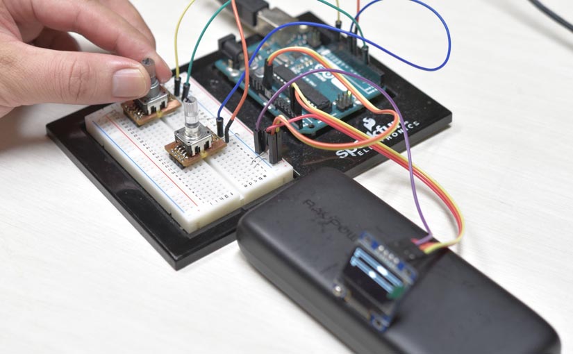
Wiring
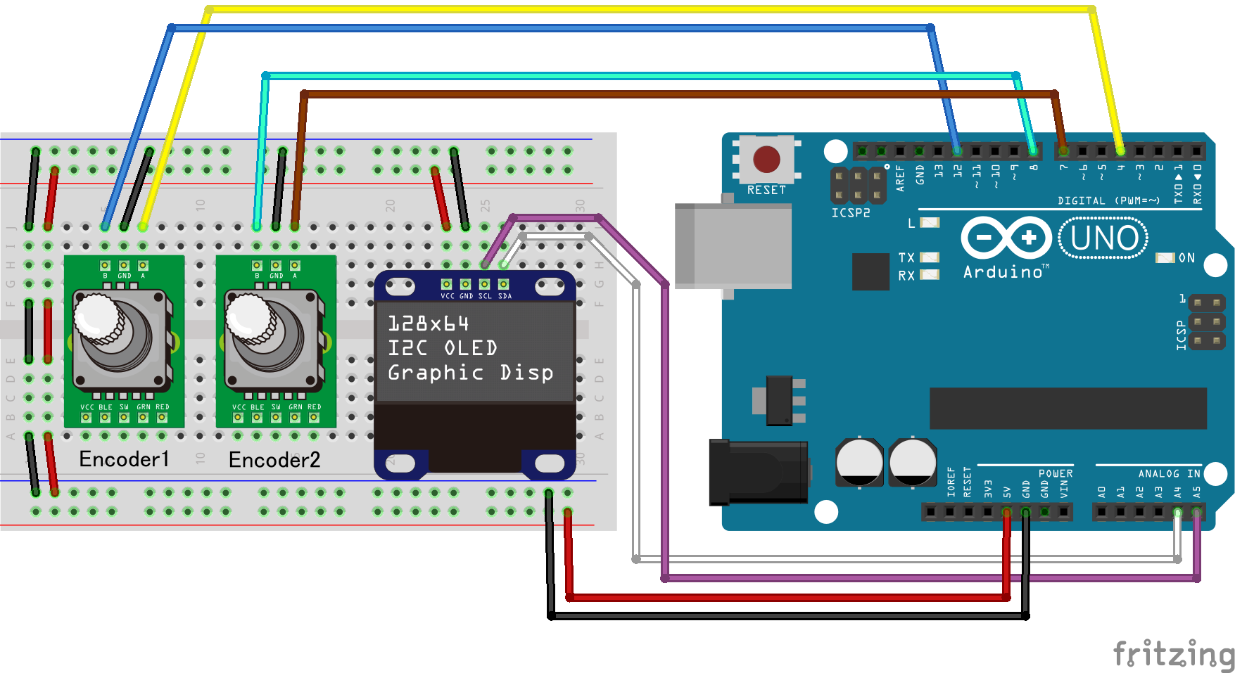
The parts necessary to try this sketch are:
- ArduinoUNO
- Rotary encoder ×2
- (if you have)128*64 OLED
Needed encoders are normal type which has 3 pins, phase1 and phase2 and GND. I recommend you to use non-click-type as in part 2.
Study about u8glib and OLED here.
Or, you don’t have to prepare it if Serial Monitor is enough for you.
Sketch
Write the sketch to Arduino by download project file or copy & paste from the code down below.
Download – 「Dual encoder ver 1.0」
//   jumbleat.com                                 //
//                                                //
//           dual encoder version 1.0             //
//                                   by jumbler   //
//                                   2017.10.20   //


#include <MsTimer2.h>
#define TIM MsTimer2

#define OLED_DRAW 1

#if(OLED_DRAW)

#include <U8glib.h>
U8GLIB_SSD1306_128X64 u8g(U8G_I2C_OPT_NONE | U8G_I2C_OPT_DEV_0); // OLED / I2C / TWI
// SDA 4/ SDL 5

#endif

#define ENC_NUM       2
#define ENC_TOLERANCE 25
#define TIMER_INTVAL  2
#define ENC_REPEAT    ENC_TOLERANCE * (TIMER_INTVAL / 2)

#define ENCA_1 4
#define ENCA_2 12
#define ENCB_1 7
#define ENCB_2 8
byte enc_pins[ENC_NUM * 2] = {ENCA_1, ENCA_2, ENCB_1, ENCB_2};


#define ECUR B00000011  // current  enc position
#define EHOM B00001100  // previous enc position
#define ECHG B01000000  // flag that encoder has changed
#define ERES B10000000  // encoder resolution. '1' is for quarter resolution
volatile int  enc_count[ENC_NUM];
volatile int  enc_old[ENC_NUM];
volatile byte enc_status[ENC_NUM];


byte ELAYER(byte layer) {
  for (byte i = 0 ; i < 8 ; i++) if ((layer >> i) & B00000001) return i;
}
byte EMASK(byte val, byte layer) {
  byte tmp = (val & layer) >> ELAYER(layer);
  return tmp;
}

bool ENC_CHECK() {
  bool yes_no = false;
  for (byte i = 0 ; i < ENC_NUM ; i++) yes_no |= ENC_CHECK(i);
  return yes_no;
}

bool ENC_CHECK(byte pin) {
  bool yes_no = enc_status[pin] & ECHG;
  return yes_no;
}

void SET_ENC_RES(byte pin, bool res) {
  if (pin < ENC_NUM)
  {
    enc_status[pin] = (enc_status[pin] & ~ERES) | (res << ELAYER(ERES));
    enc_status[pin] &= ~ECHG;
  }
}

void ENC_RESET() {
  for (byte i = 0 ; i < 5 ; i++) ENC_READ();
  for (byte i = 0 ; i < (ENC_NUM) ; i++)
  {
    enc_status[i] |= ECHG;  // kick flag
    enc_count[i]   = 0;
    ENC_COUNT(i);
    enc_status[i] |= ECHG;  // kick flag
  }
}

int ENC_COUNT(byte pin) {

  int  enc_val = 0;
  char vec     = (enc_status[pin] & ERES) ? 4 : 1;

  if (enc_status[pin] & ECHG)
  {
    enc_val  = (enc_count[pin] - enc_old[pin]) / vec;

    enc_old[pin] = enc_count[pin];  //update as previous value
    enc_status[pin] &= ~ECHG;       // reset counting flags
  }
  return enc_val;
}


void ENC_READ() {
  static byte enc_gauge[ENC_NUM];

  // read pins value
  for (byte ii = 0 ; ii < ENC_REPEAT ; ii++)
  {
    short pin_val[ENC_NUM];

    // get current pins status of Encoder1
    pin_val[0]  = ((PIND & _BV(4)) ? 1 : 0) << 1; // ENC A-1
    pin_val[0] |= ((PINB & _BV(4)) ? 1 : 0);      // ENC A-2

#if(ENC_NUM > 1)

    // get current pins status of Encoder2
    pin_val[1]  = ((PIND & _BV(7)) ? 1 : 0) << 1; // ENC B-1
    pin_val[1] |= ((PINB & _BV(0)) ? 1 : 0);      // ENC B-2

#endif


    // for each encoder pins
    for (byte i = 0 ; i < ENC_NUM ; i++)
    {
      // modify order of pins value
      if (pin_val[i] < 2) pin_val[i] = 1 + (pin_val[i] * -1);
      enc_status[i] = (enc_status[i] & ~ECUR) + pin_val[i];

      short pos_old = EMASK(enc_status[i], EHOM);

      if (pin_val[i] != pos_old)
      {
        //gauging
        enc_gauge[i] = min(ENC_TOLERANCE + 1, enc_gauge[i]++);

        //counting
        if (enc_gauge[i] >= ENC_TOLERANCE)
        {
          // increase or decrease ?
          bool dir = (pin_val[i] > pos_old) ? 1 : 0;
          if (pin_val[i] == 0 && pos_old == 3) dir = 1;
          else if (pin_val[i] == 3 && pos_old == 0) dir = 0;

          // add count by the direction
          if (dir) enc_count[i]++;
          else enc_count[i]--;

          boolean change_flag = false;

          // forced count correction for Click-type
          if (enc_status[i] & ERES)
          {
            if (pin_val[i] == 3)
            {
              char rem = enc_count[i] % 4;
              if (rem != 0)
              {
                enc_count[i] = (enc_count[i] / 4) * 4;
                if (abs(rem) > 2)
                {
                  char vec = (enc_count[i] < 0) ? -1 : 1;
                  enc_count[i] += 4 * vec;
                }
              }
              change_flag = true;
            }
          } else {
            change_flag = true;
          }

          if (enc_count[i] == enc_old[i]) change_flag = false;

          // update current pos to home pos
          enc_status[i] = (enc_status[i] & ~EHOM) | (pin_val[i] << ELAYER(EHOM));
          // set count change flag
          enc_status[i] |= change_flag << ELAYER(ECHG);
          enc_gauge[i] = 0;
        }
      } else {
        enc_gauge[i] = max(0, enc_gauge[i]--);
      }
    }
  }
}


void setup() {
  for (byte i = 0 ; i < (ENC_NUM * 2) ; i++) pinMode(enc_pins[i], INPUT_PULLUP);

  SET_ENC_RES(0, 1);   // SET_ENC_RES(encoder number, click = 1 / non_click = 0)
  SET_ENC_RES(1, 1);   // SET_ENC_RES(encoder number, click = 1 / non_click = 0)

  TIM::set(TIMER_INTVAL, ENC_READ);
  TIM::start();

  Serial.begin(38400);

  char title[2][21] = {"Dual Encoder ver 1.0", "by jumbleat.com"};
  Serial.println(title[0]);
  Serial.println(title[1]);

#if(OLED_DRAW)

  u8g.setColorIndex(1);              // OLED pixel on
  u8g.setFont(u8g_font_orgv01r);     //719 Byte  / 11x11 /*

  u8g.firstPage();
  do {
    u8g.setPrintPos(15, 20);
    u8g.print(title[0]);
    u8g.setPrintPos(50, 55);
    u8g.print(title[1]);
  } while (u8g.nextPage());

#endif

  delay(3000);

  ENC_RESET();
}


void loop() {
  static int val[ENC_NUM];

  if (ENC_CHECK())
  {
    for (byte i = 0 ; i < ENC_NUM ; i++)
    {
      val[i] += ENC_COUNT(i);
      Serial.print((char)('A' + i));
      Serial.print(":");
      Serial.print(val[i]);
      Serial.print("  ");
    }
    Serial.println();


#if(OLED_DRAW)

    // --- OLED Draw
    int val_draw[ENC_NUM];
    for (byte i = 0 ; i < ENC_NUM ; i++) val_draw[i] = constrain(val[i], -64, 64);

    u8g.firstPage();
    do {
      for (byte i = 0 ; i < ENC_NUM ; i++)
      {
        byte space = 16;
        u8g.drawFrame(0, i * space, 127, 4);
        u8g.drawBox(min(64, 64 + val_draw[i]), i * space, abs(val_draw[i]), 4);
        u8g.setPrintPos(0, 10 + i * space);
        u8g.print(val[i]);
      }
    } while (u8g.nextPage());
    // --- OLED Draw end

#endif

  }
}
Note
Timer interrupt
This sketch uses “MsTimer2” library to read encoder. So get it in your IDE if you haven’t imported yet.
Or you could use another timer library if you rewrite it directly.
#include <MsTimer2.h>
#define TIM MsTimer2

#define OLED_DRAW 1
void setup() {
  for (byte i = 0 ; i < (ENC_NUM * 2) ; i++) pinMode(enc_pins[i], INPUT_PULLUP);

  SET_ENC_RES(0, 1);   // SET_ENC_RES(encoder number, click = 1 / non_click = 0)
  SET_ENC_RES(1, 1);   // SET_ENC_RES(encoder number, click = 1 / non_click = 0)

  TIM::set(TIMER_INTVAL, ENC_READ);
  TIM::start();
Port registers
This time, I used ‘Port registers’ not ‘digitalRead’ because it is more efficient.
So you can’t change pins easily. And it won’t work on Arduino which has different port number.
Please make it change by yourself if you need modify.
“PIN# & _BV(#)” are the pin setting.
Ref ) Port of ArduinoUNO
void ENC_READ() {
  static byte enc_gauge[ENC_NUM];

  // read pins value
  for (byte ii = 0 ; ii < ENC_REPEAT ; ii++)
  {
    short pin_val[ENC_NUM];

    // get current pins status of Encoder1
    pin_val[0]  = ((PIND & _BV(4)) ? 1 : 0) << 1; // ENC A-1
    pin_val[0] |= ((PINB & _BV(4)) ? 1 : 0);      // ENC A-2

#if(ENC_NUM > 1)

    // get current pins status of Encoder2
    pin_val[1]  = ((PIND & _BV(7)) ? 1 : 0) << 1; // ENC B-1
    pin_val[1] |= ((PINB & _BV(0)) ? 1 : 0);      // ENC B-2

#endif
By the way, the pins defining for pinMode needs to be changed too.
#define ENC_NUM       2
#define ENC_TOLERANCE 25
#define TIMER_INTVAL  2
#define ENC_REPEAT    ENC_TOLERANCE * (TIMER_INTVAL / 2)

#define ENCA_1 4
#define ENCA_2 12
#define ENCB_1 7
#define ENCB_2 8
byte enc_pins[ENC_NUM * 2] = {ENCA_1, ENCA_2, ENCB_1, ENCB_2};
How to use Dual Encoder
Basically, simply use ENC_COUNT(#) function. You can use it anywhere you want after staring timer interrupt.
Read part 1 and part 2 if you want to know how “Dual Encoder” works.
Inefficient update on the sketch is caused of u8glib. Change the define value of ‘OLED_DRAW’ to 0 if you want to kill it. And check the values on Serial Monitor.
#include <MsTimer2.h>
#define TIM MsTimer2

#define OLED_DRAW 1

#if(OLED_DRAW)

#include <U8glib.h>
U8GLIB_SSD1306_128X64 u8g(U8G_I2C_OPT_NONE | U8G_I2C_OPT_DEV_0); // OLED / I2C / TWI
// SDA 4/ SDL 5

#endif
Functions of ‘Dual Encoder’
void SET_ENC_RES (byte encoder num, bool resolution);
This set the resolution of the rotary encoder to use. There is no return value.
If you set ‘resolution’ to 1, it works as click-type.
| encoder num | Designation of encoder number. The first encoder is (0), the second one is (1). |
| resolution | Specification of resolution 0(false) Non-click type 1(true) Click type |
If you want to the first encoder as click type,
SET_ENC_RES(0, true);
You don’t need to use this function if you use non-click type encoder. Default of this sketch is use of non-click type.
boolean ENC_CHECK (); / ENC_CHECK (byte encoder num);
This function is for check whether the encoder is counted or not. If there has change, it returns 1(true) otherwise 0(false).
| encoder num | Designation of encoder number. The first encoder is (0), the second one is (1). |
In case of ENC_CHECK (), it returns true if there is increase / decrease from any encoder.
On the other hand, ENC_CHECK(#) returns true when the specifed one has changes.
The difference-value of ENC_COUNT() is updated if you call it. So use this function when you don’t want to update the value.
The return value of this function is reset after call “ENC_COUNT(#);”.
int ENC_COUNT (byte encoder num);
This function returns difference-value of encoder count from previous call.
| encoder num | Designation of encoder number. The first encoder is (0), the second one is (1). |
Use this function like this. If you want count of the first encoder,
val += ENC_COUNT(0);
On this sketch, you may feel it slow because of u8glib. But the actual count of the encoder would be accurate, if it won’t catch chatterings.
The return value of “ENC_CHECK();” function is reset after call this.
void ENC_RESET()
There are ‘enc_count[]’ variable on the sketch to read continuous count of each encoder. This function reset the variables. This variable is set as int type. But it may overflows in case. Avoid the case by using this function.
reference) range of ‘int’ -32,768 ~ 32,768
define
ENC_NUM
It specify the number of encoders.
Reduce value if you use single encoder, because it reduces the load too. Don’t forget rewrite defines of pins.
#define ENC_NUM       1
#define ENC_TOLERANCE 25
#define TIMER_INTVAL  2
#define ENC_REPEAT    ENC_TOLERANCE * (TIMER_INTVAL / 2)

#define ENCA_1 4
#define ENCA_2 12
//#define ENCB_1 7
//#define ENCB_2 8
byte enc_pins[ENC_NUM * 2] = {ENCA_1, ENCA_2};
ENC_TOLERANCE
As you know from part 2, this sketch use “gauging” to avoid chattering. This is the value.
You can’t set this value over 255.
TIMER_INTVAL
This value is interval time of timer interrupt (ms).
If you reduce the value, accuracy of encoder reading is raised. But it may cause to worse response of whole sketch. Opposite, raising the value solves the problem although give up accuracy of encoder reading.
ENC_REPEAT
This is repeat times of “gauging” on one time of timer interrupt. This value also affects to the response of whole task.
You can’t set this value over 255.
ENC_TOLERANCE / TIMER_INTVAL / ENC_REPEAT, balance of those values affects accuracy of encoder reading and response of the sketch. Find proper value balance in your project.
Expansion
Although the purpose of this sketch is use two encoder, you can add more encoder by little rewrite.
I tried use four encoder.
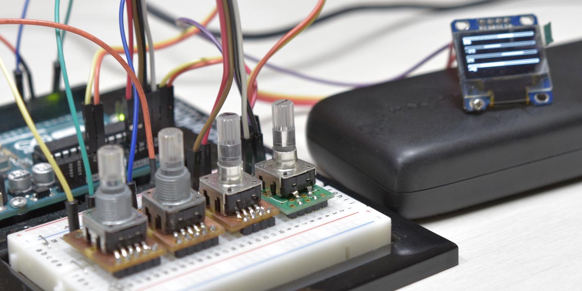
But this affects timer interrupt duration. So be careful.
This is example when you want to add third encoder.
pin define
#define ENC_NUM       3
#define ENC_TOLERANCE 25
#define TIMER_INTVAL  2
#define ENC_REPEAT    ENC_TOLERANCE * (TIMER_INTVAL / 2)

#define ENCA_1 4
#define ENCA_2 12
#define ENCB_1 7
#define ENCB_2 8
#define ENCC_1 A0
#define ENCC_2 A1
byte enc_pins[ENC_NUM * 2] = {ENCA_1, ENCA_2, ENCB_1, ENCB_2, ENCC_1, ENCC_2};
port resister
    // get current pins status of Encoder1
    pin_val[0]  = ((PIND & _BV(4)) ? 1 : 0) << 1; // ENC A-1
    pin_val[0] |= ((PINB & _BV(4)) ? 1 : 0);      // ENC A-2

#if(ENC_NUM > 1)
    // get current pins status of Encoder2
    pin_val[1]  = ((PIND & _BV(7)) ? 1 : 0) << 1; // ENC B-1
    pin_val[1] |= ((PINB & _BV(0)) ? 1 : 0);      // ENC B-2

    pin_val[2]  = ((PINC & _BV(0)) ? 1 : 0) << 1; // ENC C-1
    pin_val[2] |= ((PINC & _BV(1)) ? 1 : 0);      // ENC C-2
#endif
The new encoder number will be (2).
int val += ENC_COUNT(2);
Although there may be no such projects that handle multiple rotary encoders in many cases. But I think this sketch will work well even if a single encoder.
- Using rotary encoder Part 1 : AttachInterrupt
- Using rotary encoder Part 2 : Non-Click type
- Using rotary encoder Part 3 : Dual Encoder
Reference Site