目次 [ Contents ]
Previously, I tried to control DSLR’s shutter with IR. This time, I’m going to use “IR Remote” library which is available on Arduino IDE. This library is very useful and easy.
I used to make IR pulse by myself, but I don’t have to do that if I use this library. You can get IR binary from consumer electronics easily and send any IR commands.
Preparation
Electronic parts
- Arduino
- Infrared receiver module
- Infrared LED & Resistance
- home electronics remote control
- tact switch × 2
- Normal LED & Resistance — if you have
I recommend you to use 3.3V arduino because most of IR LED is works on lower voltage than 5V. But, several site uses 5V arduino unintentionally and it doesn’t seem to be a problem. So you may check its work with 5V if you don’t care that it may destroy those parts.
This set need to be a pair if you want to try the last sample sketch.
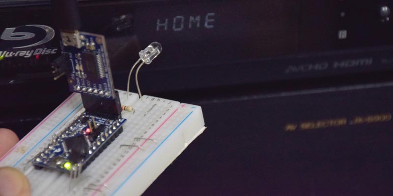
The “home electronics remote control” on this article is Sony’s Blu-ray player remote control.

I used IR receiver module ‘GP1UXC41QS‘ and ‘OSRB38C9AA‘. But there are no big differences in pins between similar modules, I think.

On this part’s data seat, they recommend to use 47 ohm resistor and 47μF capacitor. Make it check your own.
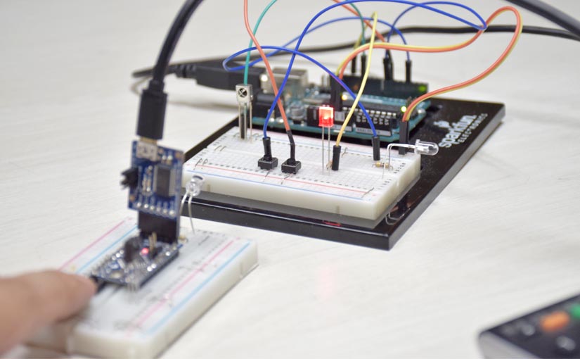
Wiring

- D03 pin : IR LED
- D07 pin : tact switch
- D11 pin : IR Reciever
- D13 pin : normal LED
There are three pins, VCC, GND, and signals on receiver module. Please be aware that the pin arrangement differs depending on the object.
On the “IR Remote” example sketches, D11 pin is used for infrared signal reception and D3 pin is for infrared transmission (PWM). So this wiring is followed it.
Also, normal LED isn’t needed if you can satisfy with LED(D13) on Arduino board.
Using “IR Remote”
The most easy way to learn IR remote is to use its example sketches.
Monitoring received IR data
Checking data of home electronics remote control is very easy with IR remote. Just open example “IRrecvDump”.
‘File’ menu → ‘example’ → ‘IRremote’ → ‘IRrecvDump’
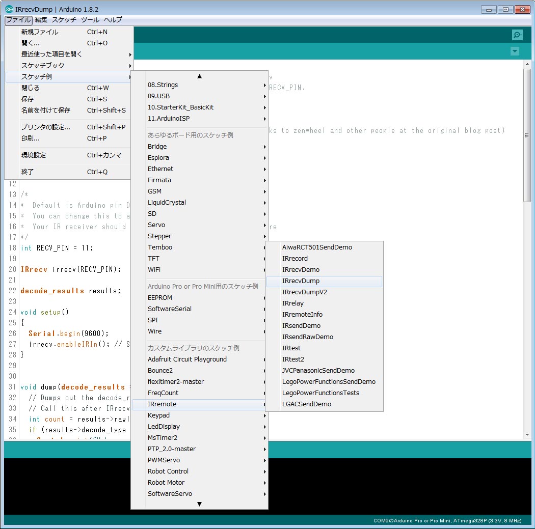
Open the serial monitor (9600 kbps), press the button on the home appliance remote control, then the data will be acquired and displayed.
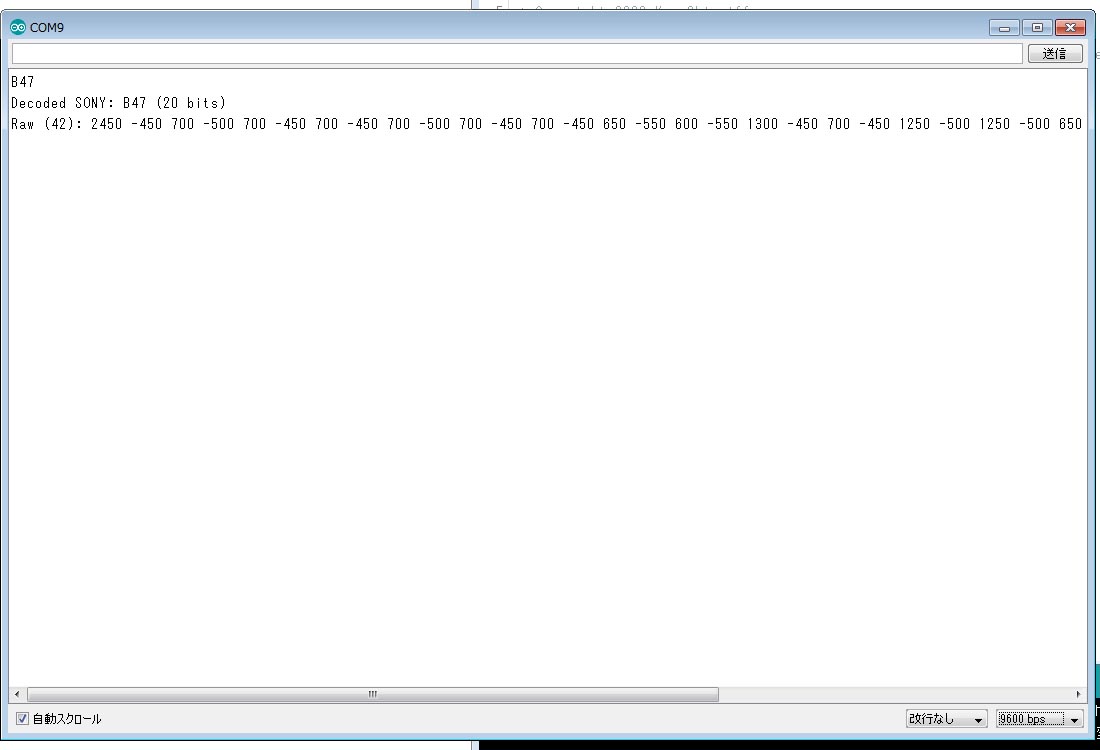
First line is the actual data (HEX notation). The next line is name of the manufacturer of the remote control. IR Remote will identify the manufacturer name somehow from the contents of the data.
The infrared transmission format has differences on concrete method with different manufacturer although it has standard rules in a part. You can learn the difference on here.
And the last line means duration of each binary. In short, these are times of IR signal inversion from last one.
Functions of “IR Remote”
Explains its functions with example ‘IRrecvDump’. Check here for more detail.
IRrecv ~(pin number);
Create an object to use for reception. In this example, ‘irrecv’ is the name of object, and ‘pin number’ is digital pin number on arduino.
int RECV_PIN = 11;

IRrecv irrecv(RECV_PIN);
~.enableIRIn();
Starting infrared reception by interrupt with created object.
void setup()
{
  Serial.begin(9600);
  irrecv.enableIRIn(); // Start the receiver
}
decode_results ~~;
Making object which to contains received IR data.
decode_results results;
The received data is stored in this created “results”. There are multiple pieces of information in it, you can specify and obtain arbitrary information.
| name | explanation |
| decode_type | name of manufacturer |
| value | command code (received byte data) |
| bits | Number of bits of command code (received byte data) |
| rawbuf[] | Array of times (μsec) for every infrared changing on or off. |
| rawlen | size of the ‘rawbuf[]’ array. |
You can easily get command code. For example,
long recv_data = results.value;
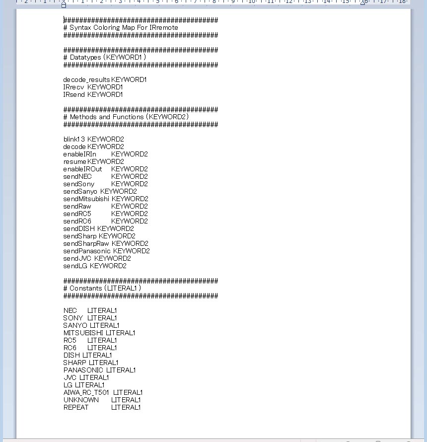
By the way, the name of manufacturer are defined. You can see the characters by the ‘KEYWORD’ file which is in library folder.
~.decode(&~~);
This function confirms whether it has been received. It returns ‘true’ when IR data is received, and ‘false’ is “not received”. It is same as “serial.available” of serial communication.
void loop() {
  if (irrecv.decode(&results)) {
    Serial.println(results.value, HEX);
    dump(&results);
    irrecv.resume(); // Receive the next value
  }
}
~.resume();
It reset the return value of “.decode ()”. If you don’t use this function after received IR data, you can’t catch next data.
void loop() {
  if (irrecv.decode(&results)) {
    Serial.println(results.value, HEX);
    dump(&results);
    irrecv.resume(); // Receive the next value
  }
}
Remember that “.decode()” and “.resume()” are a pair.
Then, I write a sketch with these functions from the beginning.
#include <IRremote.h>

IRrecv irrecv(11);
decode_results results;

void setup()
{
  Serial.begin(9600);
  irrecv.enableIRIn();
}

void loop() {
  if (irrecv.decode(&results)) {
    if (results.decode_type == SONY) Serial.print("It's SONY!  ");
    Serial.println(results.value, HEX);
    irrecv.resume();
  }
}
Change code section of “SONY” for your situation.
Sometimes you may catch several data by one push. Solve the problem by setting ‘delay()’ before ‘.resume()’.
“decode_type” reference: numbers and its string
| value | character string |
| -1 | UNKNOWN |
| 0 | UNUSED (estimation) |
| 1 | RC5 |
| 2 | RC6 |
| 3 | NEC |
| 4 | SONY |
| 5 | PANASONIC |
| 6 | JVC |
| 7 | SAMSUNG (estimation) |
| 8 | WHYNTER |
| 9 | AIWA_RC_T501 |
| 10 | LG |
| 11 | SANYO (estimation) |
| 12 | MITSUBISHI (estimation) |
| 13 | DISH (estimation) |
| 14 | SHARP (estimation) |
| 15 | DENON (estimation) |
| 16 | PRONTO (estimation) |
| 17 | LEGO_PF (estimation) |
Send Infrared data
Just make a object if you want to send IR data.
IRsend irsend;
However, you have to use different functions for each manufacturer.
irsend.sendNEC(data, bits)
irsend.sendSony(data, bits)
irsend.sendRC5(data, bits)
irsend.sendRC6(data, bits)
irsend.sendJVC(data, bits, repeat)
irsend.sendPanasonic(pre data, data)
irsend.sendRaw(data buf, length, hertz)
‘data’ is actual command code, and ‘bits’ are the size of the ‘data’.
Then I write a sample sketch that can read and transmit arbitrary data. Please change the line of “.send” according to your own manufacturer.
#include <IRremote.h>

#define SW  7
#define LED 13

IRrecv irrecv(11);
IRsend irsend;
decode_results results;

long cache_data;
byte cache_bits;
#define PUSH_SHORT 100

void setup()
{
  Serial.begin(9600);
  pinMode(SW, INPUT_PULLUP);
  pinMode(LED, OUTPUT);
  irrecv.enableIRIn();
}

void loop() {

  // capture IR signal
  if (irrecv.decode(&results))
  {
    // set values from IR
    cache_bits = results.bits;
    cache_data = results.value;

    // serial monitoring
    Serial.print("Memorized! ");
    SPRI();

    // LED flicker for check
    for (byte i = 0 ; i < 5 ; i++)
    {
      digitalWrite(LED, i % 2);
      delay(100);
    }

    // ready to next IR recieve
    irrecv.resume();
  }


  //----- pushed switch task -----

  int gauge;

  while (digitalRead(SW) == 0)
  {
    digitalWrite(LED, HIGH);
    gauge++;
  }

  // send IR data if switch is pushed
  if (gauge > PUSH_SHORT)
  {
    irsend.sendSony(cache_data, cache_bits);
    Serial.print("SEND! ");
    SPRI();
    irrecv.enableIRIn();  // restart IR recieve
  }
  digitalWrite(LED, LOW);
}


// Serial monitor display

void SPRI() {
  Serial.print("/ BITS:");
  Serial.print(cache_bits);
  Serial.print("  DATA:0x");
  Serial.print(cache_data, HEX);
  Serial.println();
}
This sketch keeps IR data to “cash_” and flashes LED of 13 pin when infrared data is received. Then, pressing the tact switch, IR LED will transmit the signal. You can check the command code values on serial monitor as well.
The most important thing is that ‘.enableIRIn();’ function is called after ‘.send’ function. This is because “enableRIn” has been stop by using “send”. You have to remember this if you want to use “receive” and “send” in a sketch.
Well, does it works? Directionality of IR LED is very narrow. So try several times by changing direction and distance. I had lost a lot of time to success of transmission.
Wireless communication
This is what most I wanted to mention. I mean,
You can make Arduino to wireless easily and in cheap by “IR remote”.
Although there are some problem in distance and direction at IR, it make it to instant wireless by few dollars.
So I write a sample sketch which get and send code by “IR Remote”.
Wiring
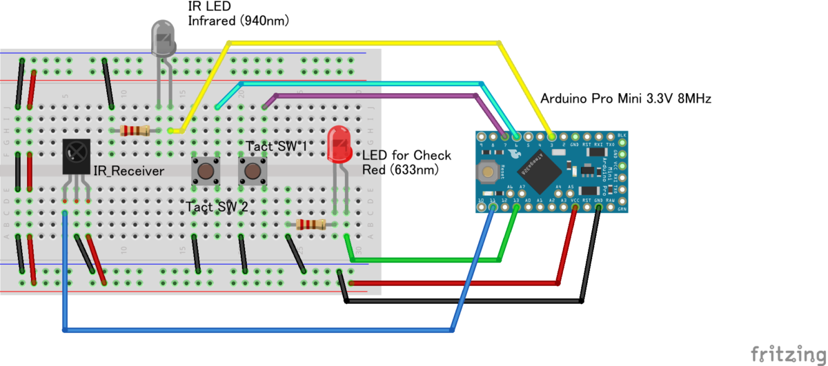
- D03 pin : IR LED
- D06 pin : tact switch 2
- D07 pin : tact switch 1
- D11 pin : IR Reciever
- D13 pin : normal LED
Just add another tact switch from previous wiring. Prepare this system by two.
Sketch “IR Controller”
Received data is cached during push of each tact switch. Then it sends the command code by normal pushing.
Change code section of “SONY” for your situation.
#include <IRremote.h>

#define SW_1 6
#define SW_2 7
#define LED  13

IRrecv irrecv(11);
IRsend irsend;
decode_results results;

#define SW_SIZE 2
byte sw_pins [SW_SIZE] = {SW_1, SW_2};
long cache_data [SW_SIZE];
byte cache_bits [SW_SIZE];
#define PUSH_SHORT 100


void setup()
{
  Serial.begin(9600);
  for (byte i = 0 ; i < SW_SIZE; i++) pinMode(sw_pins[i], INPUT_PULLUP);
  pinMode(LED, OUTPUT);
  irrecv.enableIRIn();
  Serial.println("This is IR Controller!");
}


void loop() {

  // ----- send IR data if you pushed switches -----
  for (byte i = 0 ; i < SW_SIZE ; i++)
  {
    if (FUNC_SW(i) == true)
    {
      irsend.sendSony(cache_data[i], cache_bits[i]);

      Serial.print("SEND SW:");
      Serial.print(i + 1);
      Serial.print("! ");
      SPRI(i);
      delay(40);
      irrecv.enableIRIn();  // restart IR recieve function
    }
    digitalWrite(LED, LOW);
  }

  // -----  task for each recieving -----

  if (irrecv.decode(&results))
  {

    // --- Switch 1 reaction

    if (cache_data[0] == results.value)
    {
      Serial.print("Recieved! SW:1 ");
      SPRI(0);
      LED_FLICKER(20, 100);


      // --- Switch 2 reaction

    } else if (cache_data[1] == results.value) {
      Serial.print("Recieved! SW:2 ");
      SPRI(1);
      LED_FLICKER(10, 400);


      // --- non assigned switch reaction

    } else {
      Serial.print("no Assigned! ");
      Serial.print("/ BITS:");
      Serial.print(results.bits);
      Serial.print("  DATA:0x");
      Serial.println(results.value, HEX);
    }

    irrecv.resume();
    digitalWrite(LED, LOW);
  }
}


boolean FUNC_SW(byte pins) {
  int  gauge;
  bool pushed = true;

  while (digitalRead(sw_pins[pins]) == 0)
  {
    digitalWrite(LED, HIGH);
    if (pushed == true) gauge++;

    // capture IR signal
    if (irrecv.decode(&results))
    {
      // set values from IR
      cache_bits[pins] = results.bits;
      cache_data[pins] = results.value;

      // serial monitoring
      Serial.print("Memorized to SW:");
      Serial.print(pins + 1);
      Serial.print("! ");
      SPRI(pins);

      LED_FLICKER(5, 100);

      // ready to next IR recieve
      irrecv.resume();
      pushed = false;
      gauge  = 0;
    }
  }

  if (gauge < PUSH_SHORT) pushed = false;
  digitalWrite(LED, LOW);

  return pushed;
}


// LED flicker for check

void LED_FLICKER(byte times, short dur) {
  for (byte i = 1 ; i <= times ; i++)
  {
    digitalWrite(LED, i % 2);
    delay(dur);
  }
  digitalWrite(LED, LOW);
}


// Serial monitor display

void SPRI(byte pins) {
  Serial.print("/ BITS:");
  Serial.print(cache_bits[pins]);
  Serial.print("  DATA:0x");
  Serial.print(cache_data[pins], HEX);
  Serial.println();
}
On this sample, difference of each switch is just a variation of LED flash. But you can change it by rewrite section of “Switch 1~2 reaction”. And more, you will be able to send even values if you make the same rules in advance within both Arduino.
If there is a chance next time, I would like to make “Radio control car” by IR.
reference links
- GitHub – Arduino IRremote
- ELM – 赤外線リモコンの通信フォーマット
- アキバ通いと旅 – ArduinoのIRリモコン用ライブラリ(IRremote)を徹底的に試してみる