目次 [ Contents ]
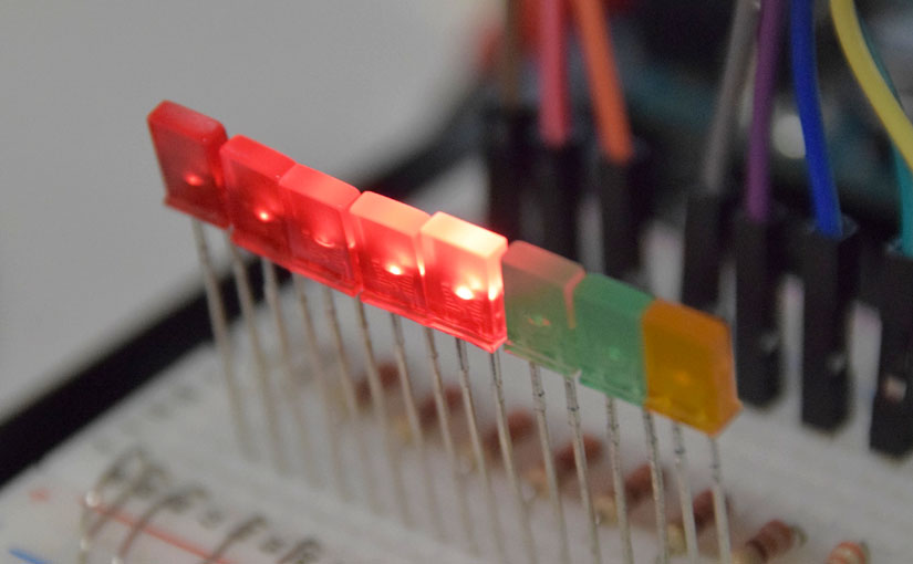
“Knight Rider” is a drama which I was looking keen in old days. In this article, I am going to imitate illuminations of the lamp on “Knight 2000”, with arduino.
To make movement of the round trip on the LED
Wiring
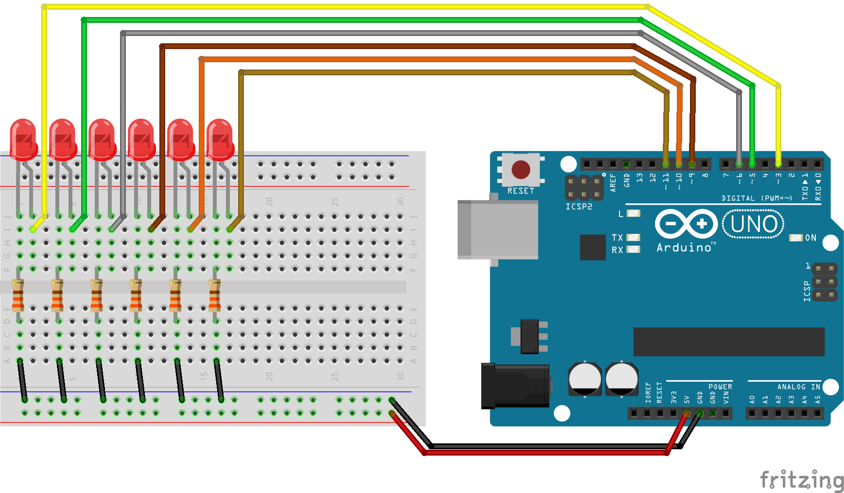
Connect Arduino pins to LED. Write a sketch to set the LED on and off in order. Basically, this is all you need. But, this way is too meaningless to be a article. So, I’m going to mention to efficient sketching.
Using ‘For’

Knight 2000 LED light flow lined, has repeatedly come repetitive motion that back and go to the end. So, you can do that with simple method by ‘HIGH’ and ‘LOW’ in ‘digitalWrite’.
digitalWrite(3, HIGH);
delay(100);
digitalWrite(3, LOW);
digitalWrite(4, HIGH);
delay(100);
digitalWrite(4, LOW....
This method is troublesome. The repetitive work is simplified by using ‘For’.
It will be simple by ‘array’ and ‘define’ pin number.
#define LED_SIZE 6
byte  leds [LED_SIZE] = {3, 5, 6, 9, 10, 11};
Now, you can repeat the work.
#define LED_SIZE 6
byte  leds [LED_SIZE] = {3, 5, 6, 9, 10, 11};


void setup() {
  // set pin to OUTPUT & LED off
  for (byte i = 0 ; i < LED_SIZE ; i++) {
    pinMode(leds[i], OUTPUT);
    digitalWrite(leds[i], LOW);
  }
}


void loop() {
  // Left to right
  for (byte repeat = 0 ; repeat < (LED_SIZE - 1) ; repeat++) {
    digitalWrite(leds[repeat], HIGH);
    delay(100);
    digitalWrite(leds[repeat], LOW);
  }

  // Right to left
  for (byte repeat = (LED_SIZE - 1) ; repeat > 0 ; repeat--) {
    digitalWrite(leds[repeat], HIGH);
    delay(100);
    digitalWrite(leds[repeat], LOW);
  }
}
“LED_SIZE – 1” is needed for stopping repeat before motion reaches to the end.
And it will be more simple by combine each repeat once.
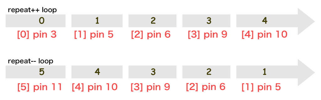
Ten times repeat is needed for total 6 LED motion. In short,
Repeat times = ( LED_SIZE-1 ) * 2
“Starting from zero” makes me confused always. Anyway, it will be a circulation following.

And if you get to the halfway point, count value need to be ‘decreased’. So I make new argument ‘count’ for that task.
#define LED_SIZE 6
byte  leds [LED_SIZE] = {3, 5, 6, 9, 10, 11};


void setup() {
  // set pin & LED off
  for (byte i = 0 ; i < LED_SIZE ; i++) {
    pinMode(leds[i], OUTPUT);
    digitalWrite(leds[i], LOW);
  }
}


void loop() {

  for (byte repeat = 0 ; repeat < ((LED_SIZE - 1) * 2) ; repeat++) {
    byte count = 0;

    if (repeat < LED_SIZE)
    {
      count = repeat ;
    } else {
      count = (LED_SIZE - 1) * 2 - repeat ;
    }

    digitalWrite(leds[count], HIGH);
    delay(100);
    digitalWrite(leds[count], LOW);
  }
}
You can separate ‘decrease’ task from ‘increase’ using ‘if’ like this.
By the way, syntax of ‘if’ is omissible.
=(Judgment formula)? value ‘TRUE’ : value ‘FALSE’;
Watch out for colon in the middle, not semicolon. It makes the sketch more simple.
#define LED_SIZE 6
byte  leds [LED_SIZE] = {3, 5, 6, 9, 10, 11};


void setup() {
  // set pin & LED off
  for (byte i = 0 ; i < LED_SIZE ; i++) {
    pinMode(leds[i], OUTPUT);
    digitalWrite(leds[i], LOW);
  }
}


void loop() {

  for (byte repeat = 0 ; repeat < ((LED_SIZE - 1) * 2) ; repeat++) {

    byte count = (repeat < LED_SIZE) ? repeat : (LED_SIZE - 1) * 2 - repeat ;

    digitalWrite(leds[count], HIGH);
    delay(100);
    digitalWrite(leds[count], LOW);
  }
}
Sketch:motion of LED
summary, so far.
#define LED_SIZE    6
#define LOOP_SIZE (LED_SIZE - 1) * 2
byte  leds [LED_SIZE] = {3, 5, 6, 9, 10, 11};


void setup() {
  // set pin to OUTPUT & LED off
  for (byte i = 0 ; i < LED_SIZE ; i++) {
    pinMode(leds[i], OUTPUT);
    digitalWrite(leds[i], LOW);
  }
}


void loop() {

  for (byte repeat = 0 ; repeat < LOOP_SIZE ; repeat++) {

    byte count = (repeat < LED_SIZE) ? repeat : LOOP_SIZE - repeat ;

    digitalWrite(leds[count], HIGH);
    delay(100);
    digitalWrite(leds[count], LOW);
  }
}
It is more simple to define total repeat time as “LOOP_SIZE”.
Variable speed
Sketch of LED motion finished. But probably you say it slow. You can change speed by value of delay, of course.
Well, why don’t you make it variable speed?
Wiring
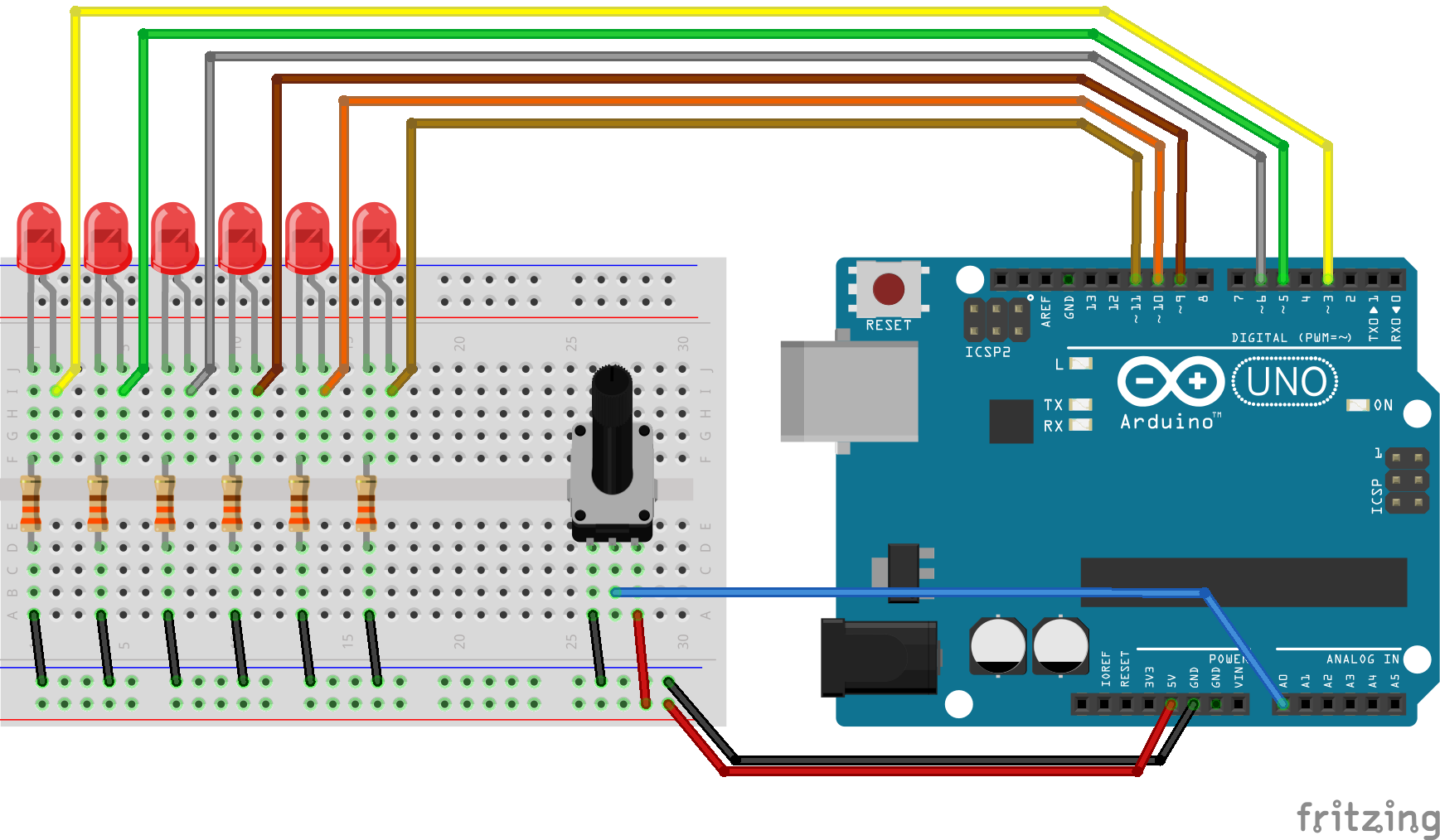
Simply connect a variable resistance to A0.
Reading a variable resistance.
Description of the analog input here will be omitted. For more information is here.
So, I will make a function of returning reasonable number of seconds (20 ms~200ms) by reading of the variable resistor.
int VOL_READ() {
  static int vol_val = 0;
  vol_val = vol_val * 0.9 + analogRead(A0) * 0.1;
  return map(vol_val, 0, 1013, 20, 200);
}
Sketch:Variable speed by a variable resistance
And set the function to the argument.
#define LED_SIZE    6
#define LOOP_SIZE (LED_SIZE - 1) * 2
byte  leds [LED_SIZE] = {3, 5, 6, 9, 10, 11};


void setup() {
  // set pin to OUTPUT & LED off
  for (byte i = 0 ; i < LED_SIZE ; i++) {
    pinMode(leds[i], OUTPUT);
    digitalWrite(leds[i], LOW);
  }
  pinMode(A0, INPUT);  // set Variable resistor
}


int VOL_READ() {
  static int vol_val = 0;
  vol_val = vol_val * 0.9 + analogRead(A0) * 0.1;
  return map(vol_val, 0, 1013, 20, 200);
}


void loop() {

  for (byte repeat = 0 ; repeat < LOOP_SIZE ; repeat++) {

    byte count = (repeat < LED_SIZE) ? repeat : LOOP_SIZE - repeat ;

    digitalWrite(leds[count], HIGH);
    delay(VOL_READ());
    digitalWrite(leds[count], LOW);
  }
}
Afterimages
Not enough? Yes, there are no afterimages on motion. We have to reproduce the afterimages.
Sketch:LED motion with the afterimages.
There is no difficult to make afterimages if you use ‘analogWrite’.
#define VOL       A0
#define LED_SIZE  6
#define LOOP_SIZE (LED_SIZE - 1) * 2
byte  leds [LED_SIZE] = {3, 5, 6, 9, 10, 11};
byte  led_luma [LED_SIZE];


void setup() {
  // set pin to OUTPUT & LED off
  for (byte i = 0 ; i < LED_SIZE ; i++) {
    pinMode(leds[i], OUTPUT);
    digitalWrite(leds[i], LOW);
  }
  pinMode(VOL, INPUT);  // set variable resistor
}


int VOL_READ() {
  static int vol_val = 0;
  vol_val = vol_val * 0.9 + analogRead(VOL) * 0.1;
  return map(vol_val, 0, 1013, 20, 200);
}


void loop() {

  for (byte repeat = 0 ; repeat < LOOP_SIZE ; repeat++)
  {
    byte led_now = (repeat < LED_SIZE) ? repeat : LOOP_SIZE - repeat;

    // reduce led luma value
    for (byte i = 0 ; i < LED_SIZE ; i++) led_luma[i] /= 3;
    // set current led luma max
    led_luma[led_now]  = 255;

    for (byte i = 0 ; i < LED_SIZE ; i++)  analogWrite(leds[i], led_luma[i]);

    delay(VOL_READ());
  }
}
Here is a trick. It becomes simple by making array of luma value for each LED. Keeping divide anyway goes to 0 in the end. And give it max value just to leads one. You can change times of afterimage by divide number.

Surveillance mode
In the drama, LED can be stopped by surveillance mode button. So, let it make.
Wiring
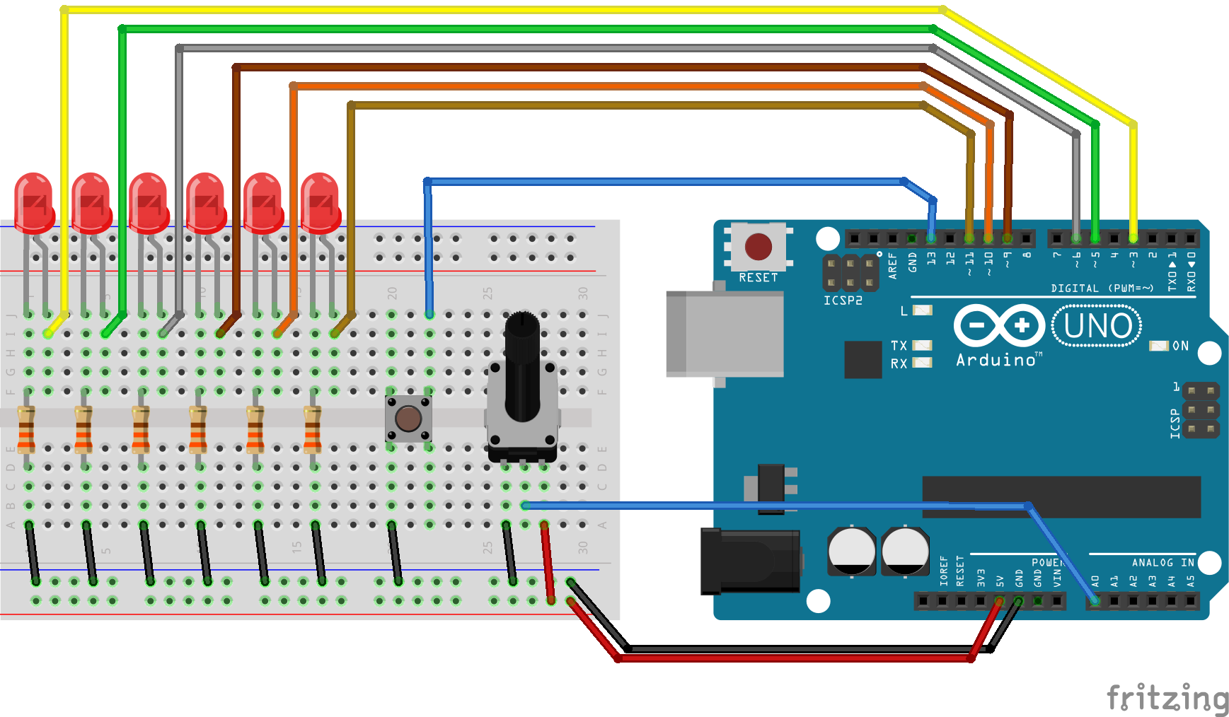
Check here, if you want to know about “switch function without chattering”.
To memorize on or off, make ‘surveillance_mode’ variable. And modify function ‘VOL_READ’ as ‘EXT_CONTROL’, which contains switch reading.
#define SW 13
#define PUSH_SHORT 700
boolean surveillance_mode = 0;
pinMode(SW, INPUT_PULLUP);

int EXT_CONTROL() {
  long button = 0;
  while(!digitalRead(SW)) button++;
  if(button > PUSH_SHORT) surveillance_mode = !surveillance_mode;

  static int vol_val = 0;
  vol_val = vol_val * 0.9 + analogRead(VOL) * 0.1;
  return map(vol_val, 0, 1013, 20, 200);
}
Sketch:Knight Rider LED
#define VOL        A0
#define SW         13
#define PUSH_SHORT 700
#define LED_SIZE   6
#define LOOP_SIZE  (LED_SIZE - 1) * 2
byte  leds [LED_SIZE] = {3, 5, 6, 9, 10, 11};
byte  led_luma [LED_SIZE];
boolean surveillance_mode = 0;


void setup() {
  // set pin to OUTPUT & LED off
  for (byte i = 0 ; i < LED_SIZE ; i++) {
    pinMode(leds[i], OUTPUT);
    digitalWrite(leds[i], LOW);
  }
  pinMode(VOL, INPUT);  // set variable resistor
  pinMode(SW, INPUT_PULLUP);  // set surveillance switch
}


int EXT_CONTROL() {
  // surveillance button function
  long button = 0;
  while (!digitalRead(SW)) button++;
  if (button > PUSH_SHORT) surveillance_mode = !surveillance_mode;

  // speed read
  static int vol_val = 0;
  vol_val = vol_val * 0.9 + analogRead(VOL) * 0.1;
  return map(vol_val, 0, 1013, 20, 200);
}


void loop() {

  EXT_CONTROL();

  for (byte repeat = 0 ; repeat < LOOP_SIZE ; repeat++)
  {
    if (surveillance_mode)
    {
      byte led_now = (repeat < LED_SIZE) ? repeat : LOOP_SIZE - repeat;

      // reduce led luma value
      for (byte i = 0 ; i < LED_SIZE ; i++) led_luma[i] /= 3;
      // set current led luma max
      led_luma[led_now]  = 255;

      for (byte i = 0 ; i < LED_SIZE ; i++) analogWrite(leds[i], led_luma[i]);
      delay(EXT_CONTROL());
    } else {
      // all led reset and off
      for (byte i = 0 ; i < LED_SIZE ; i++)
      {
        led_luma[i] = 0;
        analogWrite(leds[i], led_luma[i]);
      }
    }
  }
}
This is so simple sketch, isn’t it?
In the end
There are only six pins for PWM on Arduino UNO. So this article is modeled after the spec. But you can control more PWM pins in some other machines. Like ‘Arduino DUE’, ‘Arduino MEGA’ and ‘M0’.
In that case, you can easily expand the function. All you need is change to two arguments. For example, if you want to use 8 pin on ‘Arduino DUE’,
#define LED_SIZE   8
byte  leds [LED_SIZE] = {3, 4, 5, 6, 7, 8, 9, 10};
Max current is 20mA on Arduino. But using transistors lets you use huge LED.
I hope you will try and enjoy it.