目次 [ Contents ]
If you want to control the value step by step with Arduino, it is a quick way to ‘analogRead’ using a variable resistor. 、But, there are another way to use rotary encoder. However, if you try to implement it, there are practically difficult aspects. It is a so-called chattering problem.
I would like to write a method that can be avoiding problems encountered in using rotary encoders on this article.
If you want to use “non-click” type Rotary Encoder, check Part 2. (21/4/2017)
If you want use without “attachinterrupt”, check Part 3. (22/10/2017)
The explanation in this article is a method that I thought during make my own ‘follow focus’.
What is a rotary encoder?
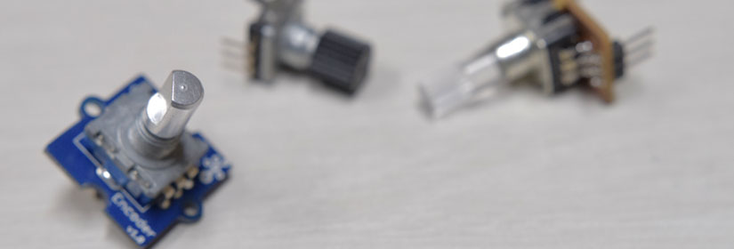
There are two types of rotary encoder, but in this article I will only deal with incremental type.
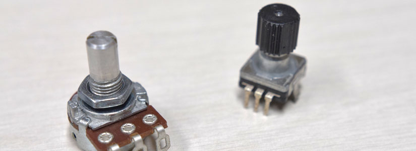
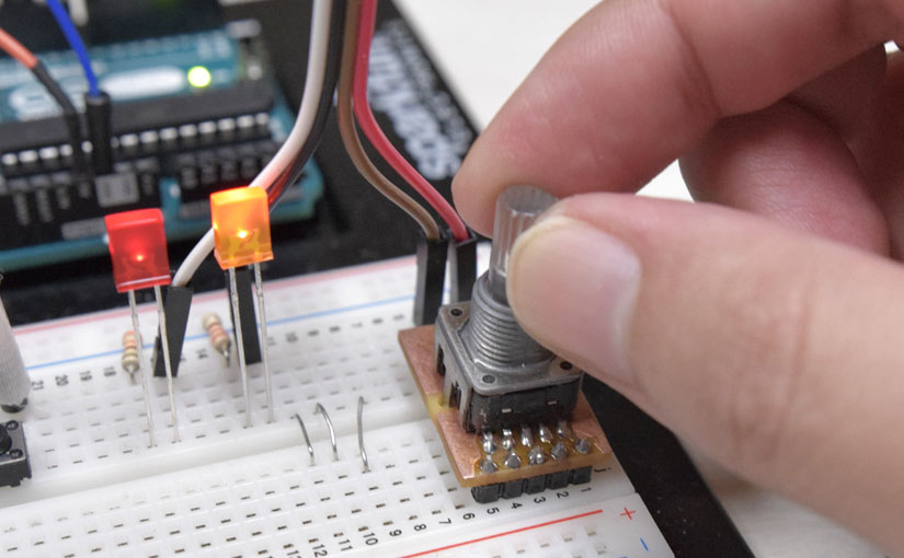
The rotary encoder is a knob that rotates just like a variable resistor. But, the structure is completely different. Its structure is a continuous switch, so it turns on and off depending on the turning angle. You can see whether this knob moved or not, by this mechanism.

However, with this, it can not tell its direction. Therefore, there are two contact points in rotary encoder, and which is slightly misaligned.
Considering the two contact states collectively, it can tell the direction by patterns. This is how a rotary encoder works.
| A | 0 | 1 | 1 | 0 | ~ |
| B | 0 | 0 | 1 | 1 | ~ |
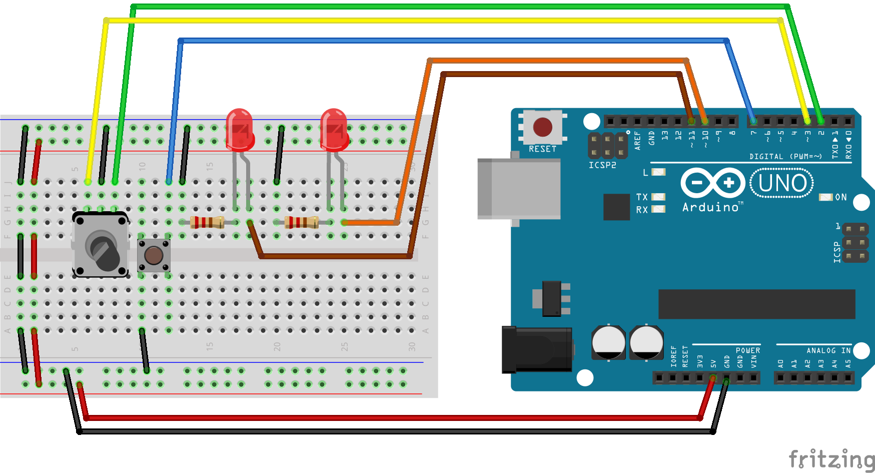
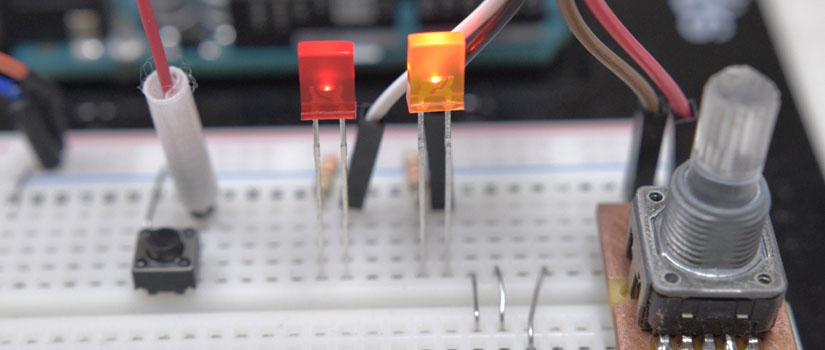
Wiring
- Rotary encoder with click function
- Tact switch
- LED & resistor * 2
Rotary encoders have two types of click and unclick. Click type have a clicking feel when it’s rotated. In this article, I will use it.
AttachInterrupt
Generally, “attachinterrupt” is used when you use rotary encoder. “attachinterrupt” is a function that monitors the state of the digital pin at all times and executes the specified function preferentially when detecting a specific change.
#define ENC_A 2
#define ENC_B 3


void setup() {
  pinMode(ENC_A, INPUT_PULLUP);
  pinMode(ENC_B, INPUT_PULLUP);

  attachInterrupt(0, ENC_READ, CHANGE);
  attachInterrupt(1, ENC_READ, CHANGE);

  Serial.begin(38400);
}


void loop() {}


void ENC_READ() {}
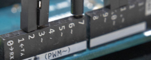
As mentioned above, it is usual to specify “attachinterrupt” in the ‘setup’ function. Although Pins that can be used for ‘attachinterrupt’ depend on the type of Arduino, but in this case, Arduino UNO has D2 and D3 pins.
attachInterrupt(0, ENC_READ, CHANGE);
attachInterrupt(1, ENC_READ, CHANGE);
In the attachInterrupt function (argument of pin number, function to be executed, condition to be executed) is specified.
Pin number
Be careful that it’s not pin numbers in Arduino but it’s number for pins which is correspond to external interrupts. For ArduinoUNO, the D2 pin is 0 and the D3 pin is 1.
Function to be executed
This is the function name to be executed when a change is detected. In this article it is set to “ENC_READ”. But like general function rule, it is OK with arbitrary name unless you use reserved function name.
Conditions to be executed
Specify what kind of state the designated pin will respond. There are several conditions, and specify it with the following character strings.
| strings | explanation |
| LOW | When the pin goes LOW |
| CHANGE | When the pin goes changed |
| RISING | When the pin goes HIGH |
| FALLING | When the pin turns to LOW from HIGH |
Reading the rotary encoder
1. Check the state
First, I will write a sketch that can always check the encoder’s status. The result is displayed on ‘serial monitor’.
#define ENC_A 2
#define ENC_B 3


void setup() {
  pinMode(ENC_A, INPUT_PULLUP);
  pinMode(ENC_B, INPUT_PULLUP);

  attachInterrupt(0, ENC_READ, CHANGE);
  attachInterrupt(1, ENC_READ, CHANGE);

  Serial.begin(38400);
}


void loop() {}


void ENC_READ() {
  bool cur[2];

  cur[0] = !digitalRead(ENC_A);
  cur[1] = !digitalRead(ENC_B);

  Serial.print("A:");
  Serial.print(cur[0]);
  Serial.print(" ");

  Serial.print("B:");
  Serial.print(cur[1]);

  Serial.println();
}
If it detect a pin change, repeat simply reading both pin states (cur [0], cur [1]) and returning the result in ‘Serial monitor’.

It supposed to be displayed only four times per a click, but it is displayed extra due to chattering. This problem will be resolved later, so let it be for now.
Assuming that the basic place is ‘W’, the pattern of both pins will change continuously to the next ‘W’ during one click. Check the summary down below.
| Pattern | X | Y | Z | W | X | Y | Z | ~ |
| D2 pin(A) | 1 | 1 | 0 | 0 | 1 | 1 | 0 | ~ |
| D3 pin(B) | 0 | 1 | 1 | 0 | 0 | 1 | 1 | ~ |
2. Dividing into patterns
Next, rewrite the sketch so that two pin states can be handled as a set. In this case, it will be simple by combine two bit into one byte with ‘bit shift’.
void ENC_READ() {
  byte cur;

  cur  = !digitalRead(ENC_B) << 1;
  cur += !digitalRead(ENC_A);

  Serial.println(cur, BIN);
}
For example,
B00000001 → B00000010
And adding ‘A’ pin status to this, you can see both status in one value ‘cur’. 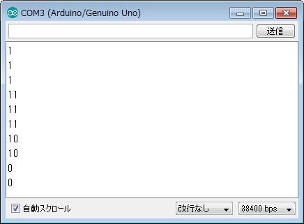
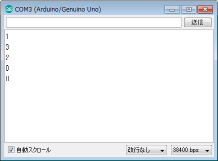
“Serial.println(cur, BIN);”, means output ‘cur’ value as binary. So by changing it to “Serial.println(cur);”, you can see it in the decimal value.
The relationship between binary numbers and decimal numbers can be summarized as follows.
| Pattern | Y | Z | W | X | Y | Z |
| binary | 11 | 10 | 00 | 01 | 11 | 10 |
| decimal | 3 | 2 | 0 | 1 | 3 | 2 |
Now, the encoder pattern can now be expressed with 2 bits. However, as array of decimal numbers are 0 – 1 – 3 – 2, it confusing. So I will rewrite it so that it is aligned in order for convenience.
void ENC_READ() {
  byte cur;

  cur = (!digitalRead(ENC_B) << 1) + !digitalRead(ENC_A);

  if (cur == 3) cur = 2;
  else if (cur == 2) cur = 3;

  Serial.println(cur);
}
| Pattern | Y | Z | W | X | Y | Z |
| decimal | 2 | 3 | 0 | 1 | 2 | 3 |
3. To detect the direction
The next step is detect the direction identification. To know the direction, you need to match with the previous pattern.
#define ENC_A 2
#define ENC_B 3

volatile byte pos;


void setup() {
  pinMode(ENC_A, INPUT_PULLUP);
  pinMode(ENC_B, INPUT_PULLUP);

  attachInterrupt(0, ENC_READ, CHANGE);
  attachInterrupt(1, ENC_READ, CHANGE);

  Serial.begin(38400);
}


void loop() {}


void ENC_READ() {
  byte cur = (!digitalRead(ENC_B) << 1) + !digitalRead(ENC_A);
  byte old = pos & B00000011;

  if (cur == 3) cur = 2;
  else if (cur == 2) cur = 3;

  bool rote = 0;
  if (cur == 3 && old == 0) rote = 0;
  else if (cur == 0 && old == 3) rote = 1;
  else if (cur > old) rote = 1;

  pos = (old << 2) + cur;

  const char vector[2] = {'<', '>'};
  Serial.print(vector[rote]);
  Serial.println(pos + 128, BIN);

}
First, we create a byte type global variable “pos”.
volatile byte pos;
On interrupt value, you must put “volatile” on declaring.
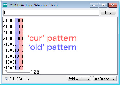
Since 2 patterns can be stored with 2 bits, we will combine this time and last time into ‘pos’.
pos = (old << 2) + cur;
B00000000 ← Blue:old Yellow:cur
byte old = pos & B00000011;
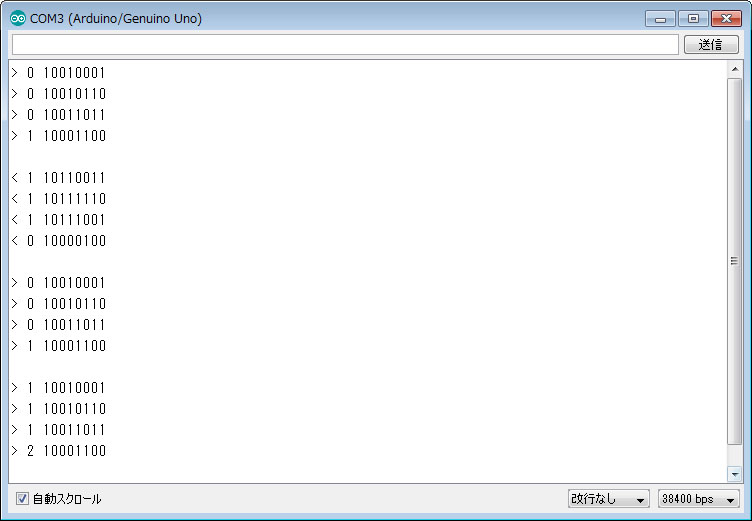
I have changed the pattern to normal number. So I can easily see it rotates forward if it increased except “0 to 3” or “0 to 3”. Now, apply it.
  bool rote = 0;
  if (cur == 3 && old == 0) rote = 0;
  else if (cur == 0 && old == 3) rote = 1;
  else if (cur > old) rote = 1;
In this way, we can get direction, get into “rote”. And “Serial monitor” displays result. By the way, a highest bit is set to HIGH (128) to prevent the number of digits of the binary display from changing on “Serial monitor”.
Serial.println(pos + 128, BIN);
Here, we add chattering countermeasures by refer the previous pattern. You can see there may be duplication between the previous time and this time on serial monitor. I change sketch so that if it is not together, it will be updated the pattern memory.
void ENC_READ() {
  byte cur = (!digitalRead(ENC_B) << 1) + !digitalRead(ENC_A);
  byte old = pos & B00000011;

  if (cur == 3) cur = 2;
  else if (cur == 2) cur = 3;

  if (cur != old)
  {
    bool rote = 0;
    if (cur == 3 && old == 0) rote = 0;
    else if (cur == 0 && old == 3) rote = 1;
    else if (cur > old) rote = 1;

    pos = (old << 2) + cur;

    const char vector[2] = {'<', '>'};
    Serial.print(vector[rote]);
    Serial.println(pos + (1 << 7), BIN);
    if (cur == 0) Serial.println();
  }
}
Although the response was improved, it is still not possible to prevent erroneous operation by chattering perfectly.

4. Counting by encoder
Based on what we have done so far, I try to count with encoder rotation. But, chattering problem is still remains. In order to avoid this, we need to change our way of thinking.
At the time, this problem was terribly annoying me, but one conclusion came out. As the one click becomes one movement with four patterns, you do not have to follow all patterns on rotary encoder. Important things are “start moving” and “end of moving”. If it is captured properly, it will be work as a count.
| Pattern | Y | Z | W | X | Y | Z |
| decimal | 2 | 3 | 0 | 1 | 2 | 3 |
| Forward | → | END | START | → | ||
| Backward | ← | START | END | ← |
So I make ‘dir’ variable to tell it whether or not you move. Then write the pattern of the starting point when you start moving, and reset to 0 when the movement is over.
if (dir == 0)
{
  if (cur == 1 || cur == 3) dir = cur;
} else {
  if (cur == 0)
{
  dir = 0;
}
There is nothing to do with patterns and chattering in the middle, if it can catches proper starting and ending.
| direction | finished judgment | achievement of rotation | |
| Forward | dir = 1 | cur = 0 | old = 3 |
| Backward | dir = 3 | cur = 0 | old = 1 |
Finally, put the ‘dir’ bit into the ‘pos’ variable.
pos = (dir << 4) + (old << 2) + cur;
Summarizing, it will be the sketch below. For counting, “enc_count” is newly prepared.
#define ENC_A 2
#define ENC_B 3

volatile byte pos;
volatile int  enc_count;


void setup() {
  pinMode(ENC_A, INPUT_PULLUP);
  pinMode(ENC_B, INPUT_PULLUP);

  attachInterrupt(0, ENC_READ, CHANGE);
  attachInterrupt(1, ENC_READ, CHANGE);

  Serial.begin(38400);
}


void loop() {}


void ENC_READ() {
  byte cur = (!digitalRead(ENC_B) << 1) + !digitalRead(ENC_A);
  byte old = pos & B00000011;
  byte dir = (pos & B00110000) >> 4;

  if (cur == 3) cur = 2;
  else if (cur == 2) cur = 3;

  if (cur != old)
  {
    if (dir == 0)
    {
      if (cur == 1 || cur == 3) dir = cur;
    } else {
      if (cur == 0)
      {
        if (dir == 1 && old == 3) enc_count++;
        else if (dir == 3 && old == 1) enc_count--;
        dir = 0;
      }
    }

    bool rote = 0;
    if (cur == 3 && old == 0) rote = 0;
    else if (cur == 0 && old == 3) rote = 1;
    else if (cur > old) rote = 1;

    pos = (dir << 4) + (old << 2) + cur;

    const char vector[2] = {'<', '>'};
    Serial.print(vector[rote]);
    Serial.print(" ");
    Serial.print(enc_count);
    Serial.print(" ");
    Serial.println(pos + (1 << 7), BIN);
    if (cur == 0) Serial.println();
  }
}
How about that? I think that it works quite accurately. If you have a complaint about response, comment out “Serial.print” in attachinterrupt. This cause to delay of precise counting.
5. Separating interrupt and count addition processing
Interrupt processing always executes immediately when there is a change. So if you try to use “enc_count” value in the main loop, it makes discrepancy. Therefore, we separate function of counting from total count value.
int ENC_COUNT(int incoming) {
  static int enc_old = enc_count;
  int val_change = enc_count - enc_old;

  if (val_change != 0)
  {
    incoming += val_change;
    enc_old   = enc_count;
  }
  return incoming;
}
By making “ENC_COUNT” function, we can get bridged value.
Summary Sketch
In the end, draw a sketch that you can individually adjust the brightness of the two LEDs with a rotary encoder. You can toggle the LED by the switch. Also you can see the values of LED on the “Serial Monitor”.
In addition, you can also add LED pins by increasing the pin numbers on “LED_SIZE” and “led_pin”.
Sketch : Brightness adjustment of LED by rotary encoder
#define ENC_A  2
#define ENC_B  3

volatile byte pos;
volatile int  enc_count;

#define LED_SW   7
#define LED_SIZE 2
const byte led_pin[LED_SIZE]  = {10, 11};   // digital pins for LED
byte       led_luma[LED_SIZE] = {255, 255}; // luma for each LED
boolean    sw = false;


void setup() {
  pinMode(ENC_A, INPUT_PULLUP);
  pinMode(ENC_B, INPUT_PULLUP);

  attachInterrupt(0, ENC_READ, CHANGE);
  attachInterrupt(1, ENC_READ, CHANGE);

  Serial.begin(38400);

  for (byte i = 0 ; i < LED_SIZE ; i++)
  {
    pinMode(led_pin[i], OUTPUT);
    analogWrite(led_pin[i], led_luma[i]);
  }
  pinMode(LED_SW, INPUT_PULLUP);
  SERIAL_MON();
}


void loop() {

  // LED switch change
  unsigned long gauge;
  while (!digitalRead(LED_SW)) gauge++;
  if (gauge > 700)
  {
    sw = !sw;
    SERIAL_MON();
  }

  // set led_luma of active LED
  short led_ref = ENC_COUNT(led_luma[sw]);
  led_ref = constrain(led_ref, 0, 255);

  // excute luma change
  if (led_luma[sw] != led_ref)
  {
    led_luma[sw] = led_ref;
    analogWrite(led_pin[sw], led_luma[sw]);
    SERIAL_MON();
  }
}


void SERIAL_MON() {
  for (byte i = 0 ; i < LED_SIZE ; i++)
  {
    Serial.print((char)(i + 'A'));
    Serial.print(":");
    Serial.print(led_luma[i]);
    if (sw == i) Serial.print("< ");
    else Serial.print("  ");
  }
  Serial.println();
}


int ENC_COUNT(int incoming) {
  static int enc_old = enc_count;
  int val_change = enc_count - enc_old;

  if (val_change != 0)
  {
    incoming += val_change;
    enc_old   = enc_count;
  }
  return incoming;
}


void ENC_READ() {
  byte cur = (!digitalRead(ENC_B) << 1) + !digitalRead(ENC_A);
  byte old = pos & B00000011;
  byte dir = (pos & B00110000) >> 4;

  if (cur == 3) cur = 2;
  else if (cur == 2) cur = 3;

  if (cur != old)
  {
    if (dir == 0)
    {
      if (cur == 1 || cur == 3) dir = cur;
    } else {
      if (cur == 0)
      {
        if (dir == 1 && old == 3) enc_count++;
        else if (dir == 3 && old == 1) enc_count--;
        dir = 0;
      }
    }
    pos = (dir << 4) + (old << 2) + cur;
  }
}