目次 [ Contents ]
There was no environment that can be finished compose all in one computer When I started it. Everybody depended on MIDI which is very very useful. MIDI makes it accomplished complicated work by dividing heavy task into sequencer and sound module. And now almost every digital music instruments supports MIDI, even if it doesn’t have MIDI port. This let it be easier to compose music. I couldn’t imagine the world would be like this.
So I will write how to send MIDI data by using Arduino.
I wrote a chattering-less switch library with “gauging” method.
(26.6.2017)
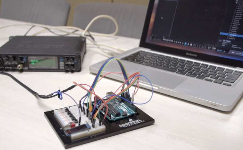
Watch this first.
Thanks to this article. This helped me to understand physical connection and protocol of MIDI.
Ready
Necessary parts
- Arduino(5V operation)
- Momentary switch
×5
- DIN 5 pin cable or connector(MIDI cable)
- Resistor 200Ω
- MIDI interface
&MIDI sound module
Additional elements
- LED&Resistor
- OLED
display
about DIN connector
There are five pins on MIDI connector. But you don’t have to wire all pins. Just 3 pin.

about MIDI interface・MIDI sound module
You need MIDI device to confirm if it were connected. You can simply connect to MIDI, if you have device like synthesizer, digital piano. In other way, there are some free music software on web.
This free version of DAW is available both Mac and Win. I used it on my Youtube demo. But in this way, you need MIDI interface.
Wiring
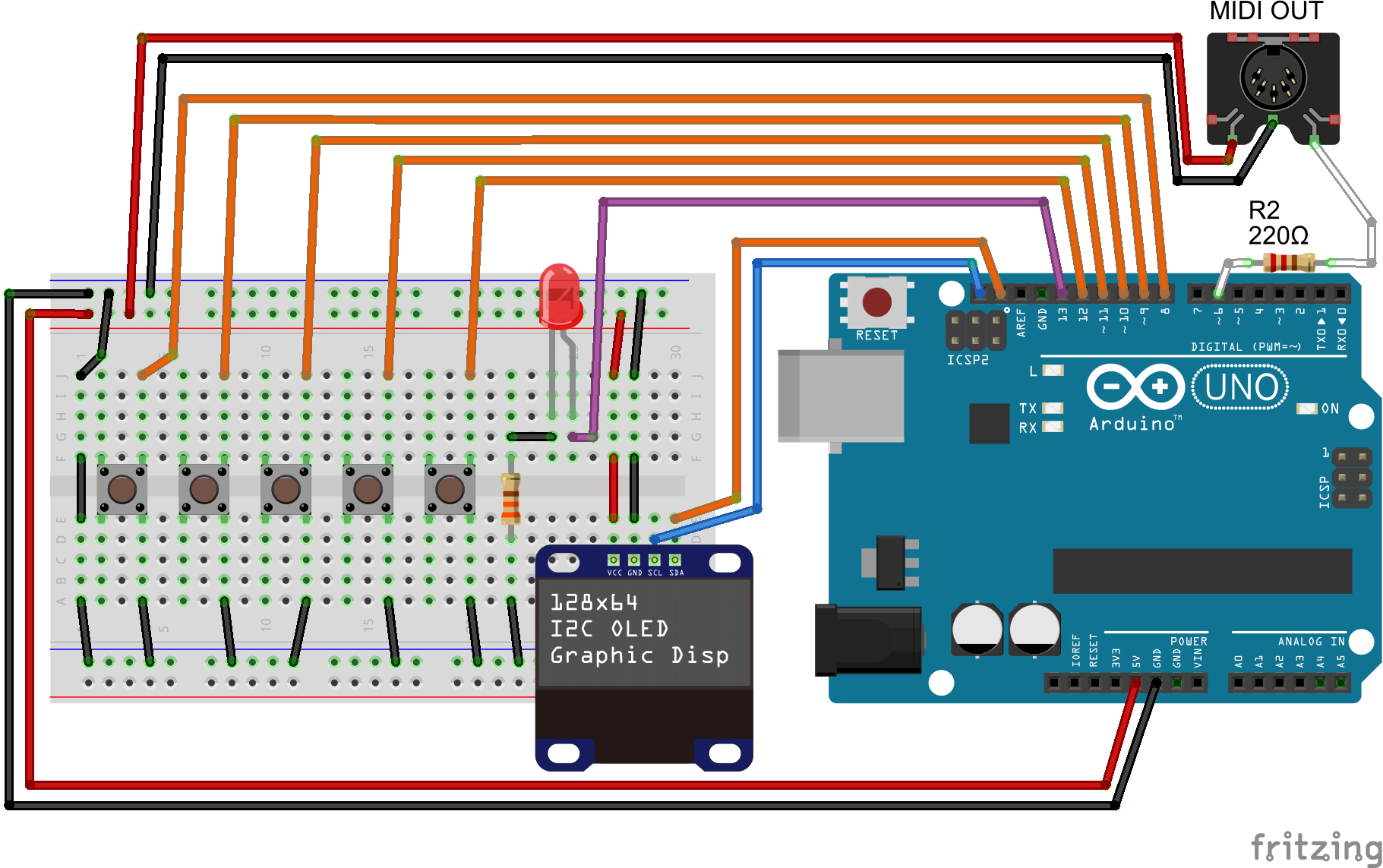
MIDI
Inside of MIDI data
The minimum necessary data to produce MIDI message is,
- channel(1~16 CH)
- note on, note off
- musical scale(note number)
- velocity
All you need is send those information as set.
MIDI message
MIDI data protocol is,
Asynchronous serial transfer of 31.25 Kbps (± 1%)
You can control MIDI device by just sending few byte. It’s same as Arduino Serial communication. So, I use ‘Software Serial’ to do it.
‘MIDI message’ is consisted by two type of data, ‘Status’ and ‘DATA’. At first is a ‘Status’ byte, this roles as header information. Then it follow to ‘DATA’ byte, containing values. This means you need 2 byte at least for each MIDI message.
Also highest bit of ‘Status’ byte must be HIGH. And its of ‘DATA’ byte is LOW.
So range of value are,
128 to 255 for value of ‘Status’ byte
0 to 127 for value of ‘DATA’ byte
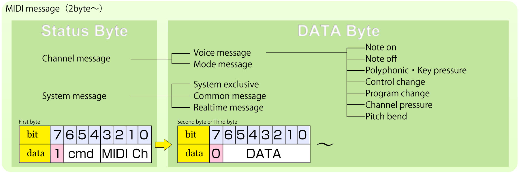
In ‘Status’ byte, lower 4 bits indicates MIDI channel and remaining 3 bits indicates type of message.
‘Note number’ means musical scale. Check down below, if you want to know array.

You have to send ‘note on’ and ‘note off’ message, if you want to play sound like do it on piano.
| first byte ‘Status’ | ‘DATA’, following the bytes | |||
| data type | higher 3bits 8 ~ 15 |
lower 4bits 0 ~ 15 |
second Byte 0 ~ 127 |
third Byte 0 ~ 127 |
| Note on | 0x90 | MIDI Ch | Note | Velocity |
| Note off | 0x80 | MIDI Ch | Note | Velocity |
These are part of MIDI message type. Check on web for further information.
Arduino Sketch
Send a MIDI message
This sketch shows most simple way to send MIDI message. MIDI channel is 2, musical scale is C-3,
#include <SoftwareSerial.h>
SoftwareSerial MIDI(5, 6); // RX, TX

//--- pins ---
#define LED 13

void setup() {
  pinMode(LED, OUTPUT);
  MIDI.begin(31250);
}

void loop() {
  // Note on message
  MIDI.write(0x91);   // Status "note on" & "MIDI Ch"
  MIDI.write(48);     // note number
  MIDI.write(127);    // velocity
  digitalWrite(LED, HIGH);

  delay(1000);

  // Note off message
  MIDI.write(0x81);   // Status "note off" & "MIDI Ch"
  MIDI.write(48);     // note number
  MIDI.write(127);    // velocity
  digitalWrite(LED, LOW);

  delay(1000);
}
This simple sketch execute play ‘C’ on MIDI sound module for each 1 second. You’d better watch out that actual MIDI channel is different from hex value.
CH 2→0x91
Below sketch is a simplified sending MIDI signal as a function.
#include <SoftwareSerial.h>
SoftwareSerial MIDI(5, 6); // RX, TX

//--- pins ---
#define LED 13

//--- MIDI ---
#define MIDI_CH  2
#define VELOCITY 127
byte notes = 48;

#define MIDI_ON  0x90|(MIDI_CH - 1)
#define MIDI_OFF 0x80|(MIDI_CH - 1)


void setup() {
  pinMode(LED, OUTPUT);
  MIDI.begin(31250);
}


void loop() {
  // Note on message
  SEND_MIDI(MIDI_ON, notes, VELOCITY);
  digitalWrite(LED, HIGH);

  delay(1000);

  // Note off message
  SEND_MIDI(MIDI_OFF, notes, VELOCITY);
  digitalWrite(LED, LOW);

  delay(1000);
}


void SEND_MIDI(byte cate, byte note, byte velo) {
  byte data[3] = {cate, note, velo};
  for (byte i = 0 ; i < 3 ; i++) MIDI.write(data[i]);
}
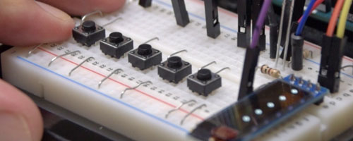
Send message by a switch
Next sample is controlling message by a switch. This function depends on “gauge switch” I developed. You don’t have to make chattering avoidance on the circuit with this sketch.
#include <SoftwareSerial.h>
SoftwareSerial MIDI(5, 6); // RX, TX

//--- pins ---
#define LED 13
#define SW  8

//--- Switch ---
#define PUSH_SHORT 700  // judgement value of pushing counter
#define SW_LIMIT   710  // counter limit

//--- MIDI ---
#define MIDI_CH  2
#define VELOCITY 127
byte notes = 48;

#define MIDI_ON  0x90|(MIDI_CH - 1)
#define MIDI_OFF 0x80|(MIDI_CH - 1)


void setup() {
  pinMode(LED, OUTPUT);
  pinMode(SW, INPUT_PULLUP);
  MIDI.begin(31250);
}


void loop() {
  short gauge;

  // pushing counter task
  while (!digitalRead(SW))
  {
    gauge++;

    // not to over limit of counter
    if (gauge > SW_LIMIT) gauge = SW_LIMIT;

    // action when pushing counter goes in range
    if (gauge == PUSH_SHORT)
    {
      SEND_MIDI(MIDI_ON, notes, VELOCITY);
      digitalWrite(LED, HIGH);
    }
  }

  // Note off message
  if (gauge >= PUSH_SHORT)
  {
    SEND_MIDI(MIDI_OFF, notes, VELOCITY);
    digitalWrite(LED, LOW);
  }
}


void SEND_MIDI(byte cate, byte note, byte velo) {
  byte data[3] = {cate, note, velo};
  for (byte i = 0 ; i < 3 ; i++) MIDI.write(data[i]);
}
Does it works? You probably got precise and easy MIDI button.
This method is very effective. But, it only does works to one switch. The problem is caused by ‘while’ loop. So I have to remove the problem.
The way is “maintain the value”.
short gauge = 0;

void loop() {

  // pushing counter task
  if (!digitalRead(SW))
  {
    gauge++;
    // not to over limit of counter
    if (gauge > SW_LIMIT) gauge = SW_LIMIT;

  } else {

    // Note off message
    if (gauge >= PUSH_SHORT)
    {
      SEND_MIDI(MIDI_OFF, notes, VELOCITY);
      digitalWrite(LED, LOW);
    }
    gauge = 0;
  }

  // action when pushing counter goes in range
  if (gauge == PUSH_SHORT)
  {
    SEND_MIDI(MIDI_ON, notes, VELOCITY);
    digitalWrite(LED, HIGH);
  }
}


void SEND_MIDI(byte cate, byte note, byte velo) {
  byte data[3] = {cate, note, velo};
  for (byte i = 0 ; i < 3 ; i++) MIDI.write(data[i]);
}
Basic thinking that several digital ‘HIGH’ determines ‘switch on’ is same.
Reading high from switch pin increases ‘gauge’ count argument. Otherwise, count is reset. Then Arduino tells ‘switch’ has been on, if count equals a certain value. Although the order on sketch has been changed, basic is same and simple.
Also I simplify it as function.
void loop() {
  byte sw_ret = BUTTON(SW);

  if (sw_ret == 1)
  {
    SEND_MIDI(MIDI_ON, notes, VELOCITY);
    digitalWrite(LED, HIGH);
  } else if (sw_ret == 255) {
    SEND_MIDI(MIDI_OFF, notes, VELOCITY);
    digitalWrite(LED, LOW);
  }
}


short gauge = 0;

byte BUTTON(byte num) {
  byte sw_status = 0;

  // pushing counter task
  if (!digitalRead(num))
  {
    gauge++;
    if (gauge > SW_LIMIT) gauge = SW_LIMIT; // not to over limit of counter
  } else {
    if (gauge > PUSH_SHORT) sw_status = 255;
    gauge = 0;
  }

  // action when switch has been pushed
  if (gauge[num] > PUSH_SHORT)  sw_status = 2;
  else if (gauge == PUSH_SHORT) sw_status = 1;

  return sw_status;
}


void SEND_MIDI(byte cate, byte note, byte velo) {
  byte data[3] = {cate, note, velo};
  for (byte i = 0 ; i < 3 ; i++) MIDI.write(data[i]);
}
‘BUTTON’ is function with a byte returning.
‘0’ is returned if the swtich is ‘OFF’.
‘1’ is returned if the switch has been changed into ‘ON’.
‘2’ is returned if the switch keep ‘ON’.
‘255’ is returned if the swtich has been changed into ‘OFF’.
Send MIDI message by the multiplex switches.
Well, it’s not so difficult to multiplex switch function. Just use array.
#include <SoftwareSerial.h>
SoftwareSerial MIDI(5, 6); // RX, TX

//--- pins ---
#define LED 13
#define PIN_NUM 5
byte pins[PIN_NUM] = {8, 9, 10, 11, 12};

//--- Switch ---
#define PUSH_SHORT 700  // judgement value of pushing counter
#define SW_LIMIT   710  // counter limit
short gauge [PIN_NUM];

//--- MIDI ---
#define MIDI_CH  2
#define VELOCITY 127
byte notes [PIN_NUM] = {48, 50, 52, 53, 55};

#define MIDI_ON  0x90|(MIDI_CH - 1)
#define MIDI_OFF 0x80|(MIDI_CH - 1)


void setup() {
  pinMode(LED, OUTPUT);
  for (byte i = 0 ; i < PIN_NUM ; i++) pinMode(pins[i], INPUT_PULLUP);
  MIDI.begin(31250);
}


void loop() {
  boolean led_stat = false;

  for (byte i = 0 ; i < PIN_NUM ; i++)
  {
    byte sw_ret = BUTTON(i);

    if (sw_ret == 1)
    {
      SEND_MIDI(MIDI_ON, notes[i], VELOCITY);
    } else if (sw_ret == 255) {
      SEND_MIDI(MIDI_OFF, notes[i], VELOCITY);
    } else if (sw_ret != 0) led_stat = true;
  }
  digitalWrite(LED, led_stat);
}


byte BUTTON(byte num) {
  byte sw_status = 0;

  // pushing counter task
  if (!digitalRead(pins[num]))
  {
    gauge[num]++;
    if (gauge[num] > SW_LIMIT) gauge[num] = SW_LIMIT; // not to over limit of counter
  } else {
    if (gauge[num] > PUSH_SHORT) sw_status = 255;
    gauge[num] = 0;
  }

  // action when pushing counter goes in range
  if (gauge[num] > PUSH_SHORT) sw_status = 2;
  else if (gauge[num] == PUSH_SHORT) sw_status = 1;


  return sw_status;
}


void SEND_MIDI(byte cate, byte note, byte velo) {
  byte data[3] = {cate, note, velo};
  for (byte i = 0 ; i < 3 ; i++) MIDI.write(data[i]);
}
‘PIN_NUM’ is total number of connected digital pins.
‘pins’ is value for each connected digital pins.
‘notes’ is MIDI note number for each switch.
You can add more switches by set the array arguments.
Incidentally, LED deponds to any switches has been ‘ON’.
External Display & turing
If you attach OLED display, you can see change. And to learn ‘gauge’ function, let’s tuning it.
#include "U8glib.h"
U8GLIB_SSD1306_128X32 u8g(U8G_I2C_OPT_NONE);  // I2C / TWI
//U8GLIB_SSD1306_128X64 u8g(U8G_I2C_OPT_NONE|U8G_I2C_OPT_DEV_0);  // I2C / TWI
//U8GLIB_SSD1306_128X64 u8g(U8G_I2C_OPT_DEV_0|U8G_I2C_OPT_NO_ACK|U8G_I2C_OPT_FAST); // Fast I2C / TWI
//U8GLIB_SSD1306_128X64 u8g(13, 11, 10, 9, 8);  // SW SPI Com: SCK = 13, MOSI = 11, CS = 10, A0 = 9

#include <SoftwareSerial.h>
SoftwareSerial MIDI(5, 6); // RX, TX

//--- pins ---
#define LED 13
#define PIN_NUM 5
byte pins[PIN_NUM] = {8, 9, 10, 11, 12};

//--- Switch ---
#define PUSH_SHORT 700  // judgement value of pushing counter
#define SW_LIMIT   PUSH_SHORT + 10  // counter limit
short gauge [PIN_NUM];
short gauge_ref[PIN_NUM];

//--- oled display ---
byte oledx, oledy;
byte h_txt;

//--- MIDI ---
#define MIDI_CH  2
#define VELOCITY 127
byte notes [PIN_NUM] = {48, 50, 52, 53, 55};

#define MIDI_ON  0x90|(MIDI_CH - 1)
#define MIDI_OFF 0x80|(MIDI_CH - 1)


void setup() {
  // oled setup
  u8g.setFont(u8g_font_6x10r);
  u8g.setColorIndex(1);
  oledx = u8g.getWidth();
  oledy = u8g.getHeight();
  h_txt = u8g.getFontAscent();

  // pins setup
  pinMode(LED, OUTPUT);
  for (byte i = 0 ; i < PIN_NUM ; i++) pinMode(pins[i], INPUT_PULLUP);

  //midi setup
  MIDI.begin(31250);
  Serial.begin(38400);
}


void loop() {
  SW_TASK();
  DRAW();
}


void DRAW() {
  u8g.firstPage();
  do {
    for (byte i = 0 ; i < PIN_NUM ; i++)
    {
      u8g.setPrintPos((oledx / PIN_NUM) * i, oledy - (h_txt * 2));
      if (gauge[i] != 0) u8g.print("-");
      else u8g.print(notes[i]);

      // gauge count display
      u8g.setPrintPos((oledx / PIN_NUM) * i, oledy);
      u8g.print(gauge_ref[i]);

      SW_TASK();
    }
  } while (u8g.nextPage());
}


void SW_TASK() {
  boolean led_stat = false;

  for (byte i = 0 ; i < PIN_NUM ; i++)
  {
    byte sw_ret = BUTTON(i);

    if (sw_ret == 1)
    {
      SEND_MIDI(MIDI_ON, notes[i], VELOCITY);
    } else if (sw_ret == 255) {
      SEND_MIDI(MIDI_OFF, notes[i], VELOCITY);
    } else if (sw_ret != 0) led_stat = true;
  }
  digitalWrite(LED, led_stat);
}


byte BUTTON(byte num) {
  byte sw_status = 0;

  // pushing counter task
  if (!digitalRead(pins[num]))
  {
    gauge[num]++;
    gauge_ref[num] = gauge[num];
    if (gauge[num] > SW_LIMIT) gauge[num] = SW_LIMIT; // not to over limit of counter
  } else {
    if (gauge[num] > PUSH_SHORT)
    {
      sw_status = 255;
    }
    if (gauge[num] > 0) SERIAL_MON();
    gauge[num] = 0;
  }

  // action when pushing counter goes in range
  if (gauge[num] > PUSH_SHORT) sw_status = 2;
  else if (gauge[num] == PUSH_SHORT) sw_status = 1;

  return sw_status;
}


void SEND_MIDI(byte cate, byte note, byte velo) {
  byte data[3] = {cate, note, velo};
  for (byte i = 0 ; i < 3 ; i++) MIDI.write(data[i]);
}

void SERIAL_MON() {
  for (byte i = 0 ; i < PIN_NUM ; i++)
  {
    Serial.print(i);
    Serial.print(":");
    Serial.print(gauge_ref[i]);
    Serial.print(" ");
  }
  Serial.println();
}
This sketch uses ‘u8glib’ library. If you want to know how to use, check here. Even if you don’t have OLED display, you can check ‘gauge’ counter value from ordinary Serial Monitor.
By the way, switch doesn’t work anymore, you think? No. This is caused by being changed ‘PUSH_SHORT’ value. Try keep push switch. There is so long delay.
#define PUSH_SHORT 700  // judgement value of pushing counter
#define SW_LIMIT   PUSH_SHORT + 10  // counter limit
So change ‘PUSH_SHORT’ value. I think the value will match over 10.
//--- MIDI ---
#define MIDI_CH  2
#define VELOCITY 127
byte notes [PIN_NUM] = {48, 50, 52, 53, 55};
You can change MIDI message from here.
‘MIDI_CH’ is channel number for sending message.
‘VELOCITY’ is velocity. Because of ‘digitalRead’, the velocity is fixed.
‘notes’ is key note scale value for each switch.
In MIDI, ch 10 is for drum. So you can play drum if you change values to below.
//--- MIDI ---
#define MIDI_CH  10
#define VELOCITY 127
byte notes [PIN_NUM] = {36, 38, 42, 51, 49}; // kick, snare, Hi-Hat, Ryde, Crash
Review
The most orthodox way to use MIDI is get Arduino Shield and use ‘MIDI library’. But in this article, I could use MIDI by only a cable and ‘Software Serial’. By furthermore learn, I maybe make physical MIDI controller, maybe..
Sketch:MIDI trigger switches
#include "U8glib.h"
U8GLIB_SSD1306_128X32 u8g(U8G_I2C_OPT_NONE);  // I2C / TWI
//U8GLIB_SSD1306_128X64 u8g(U8G_I2C_OPT_NONE|U8G_I2C_OPT_DEV_0);  // I2C / TWI
//U8GLIB_SSD1306_128X64 u8g(U8G_I2C_OPT_DEV_0|U8G_I2C_OPT_NO_ACK|U8G_I2C_OPT_FAST); // Fast I2C / TWI
//U8GLIB_SSD1306_128X64 u8g(13, 11, 10, 9, 8);  // SW SPI Com: SCK = 13, MOSI = 11, CS = 10, A0 = 9

#include <SoftwareSerial.h>
SoftwareSerial MIDI(5, 6); // RX, TX

//--- pins ---
#define LED 13
#define PIN_NUM 5
byte pins[PIN_NUM] = {8, 9, 10, 11, 12};


//--- Switch ---
#define PUSH_SHORT 10  // judgement value of pushing counter
#define SW_LIMIT   PUSH_SHORT + 10  // counter limit
short gauge [PIN_NUM];

//--- oled display ---
byte oledx, oledy;

//--- MIDI ---
#define MIDI_CH  10
#define VELOCITY 127
byte notes [PIN_NUM] = {36, 38, 42, 51, 49}; // kick, snare, Hi-Hat, Ryde, Crash
//byte notes[PIN_NUM] = {60, 62, 64, 65, 67};  // key C-D-E-F-G

#define MIDI_ON  0x90|(MIDI_CH - 1)
#define MIDI_OFF 0x80|(MIDI_CH - 1)

void setup() {
  // oled setup
  u8g.setFont(u8g_font_6x10r);
  u8g.setColorIndex(1);
  oledx = u8g.getWidth();
  oledy = u8g.getHeight();

  // pins setup
  pinMode(LED, OUTPUT);
  for (byte i = 0 ; i < PIN_NUM ; i++) pinMode(pins[i], INPUT_PULLUP);

  //midi setup
  MIDI.begin(31250);
}

void loop() {
  SW_TASK();
  DRAW();
}

void DRAW() {
  u8g.firstPage();
  do {
    for (byte i = 0 ; i < PIN_NUM ; i++)
    {
      u8g.setPrintPos((oledx / PIN_NUM) * i, oledy / 2);
      if (gauge[i] != 0) u8g.print("-");
      else u8g.print(notes[i]);
      SW_TASK();  // switch count while drawing
    }
  } while (u8g.nextPage());
}

void SW_TASK() {
  boolean led_stat = false;

  for (byte i = 0 ; i < PIN_NUM ; i++)
  {
    byte sw_ret = BUTTON(i);

    if (sw_ret == 1)
    {
      SEND_MIDI(MIDI_ON, notes[i], VELOCITY);
    } else if (sw_ret == 255) {
      SEND_MIDI(MIDI_OFF, notes[i], VELOCITY);
    } else if (sw_ret != 0) led_stat = true;
  }
  digitalWrite(LED, led_stat);
}

byte BUTTON(byte num) {
  byte sw_status = 0;

  // pushing counter task
  if (!digitalRead(pins[num]))
  {
    gauge[num]++;
    if (gauge[num] > SW_LIMIT) gauge[num] = SW_LIMIT; // not to over limit of counter
  } else {
    if (gauge[num] > PUSH_SHORT)
    {
      sw_status = 255;
    }
    if (gauge[num] > 0) SERIAL_MON();
    gauge[num] = 0;
  }

  // action when pushing counter goes in range
  if (gauge[num] > PUSH_SHORT) sw_status = 2;
  else if (gauge[num] == PUSH_SHORT) sw_status = 1;

  return sw_status;
}

void SEND_MIDI(byte cate, byte note, byte velo) {
  byte data[3] = {cate, note, velo};
  for (byte i = 0 ; i < 3 ; i++) MIDI.write(data[i]);
}