目次 [ Contents ]
I wrote a article about using MIDI by ‘Software Serial’. In this article, I also mentioned to how to ‘avoiding switches chatter’. This is new version of the method in old article. But for someone who never interested in MIDI, I write this method in this article again.
I wrote a chattering-less switch library with “gauging” method.
(26.6.2017)
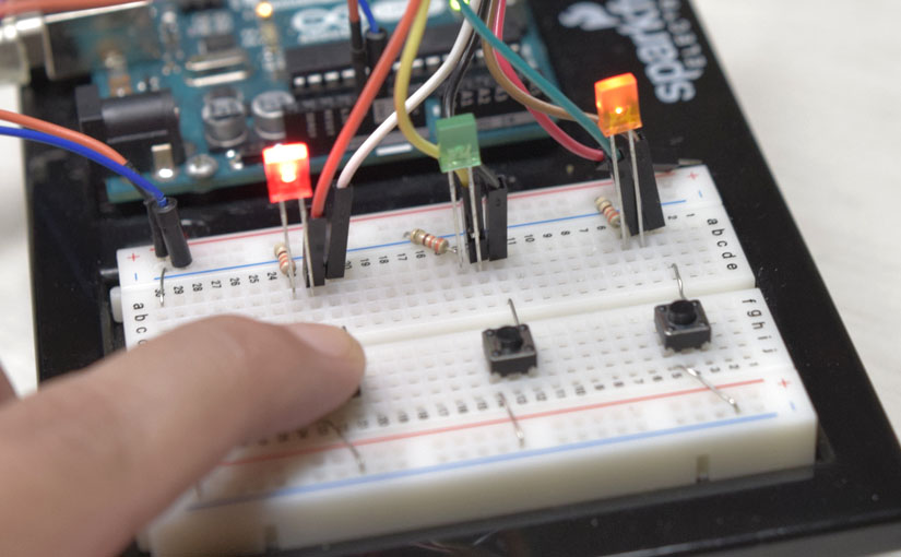
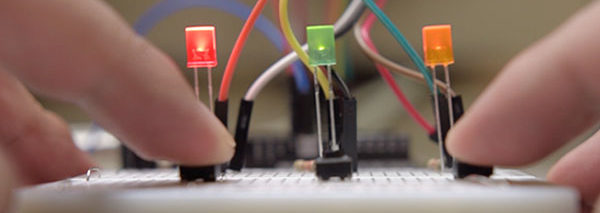
This is the video using ‘gauging method’.
You can see each switch reacts individually.
‘Switch gauging’ method
When using a switch on Arduino, it is sometimes impossible to distinguish exact ON / OFF with physical contacts by bouncing, which is called chattering. Although there are many workaround methods on the web, some methods to avoid in terms of electric circuits require separate parts, and otherside, general programming avoidance methods sacrifice accuracy. So, I invented the easiest way to ignore just chattering just by programming.
Advantage
- Simple.
- React even in repeated hits.
- You can reflect the push time.
Disadvantage
- Adjustment is required depending on the length of the sketch.
- Sketch need to be devised for using as practical functions.
In the previous article, there was only one switch, and during pressing it was a difficult way to put other instructions. However, this time I will show you how to handle even multiple switches.
Wiring
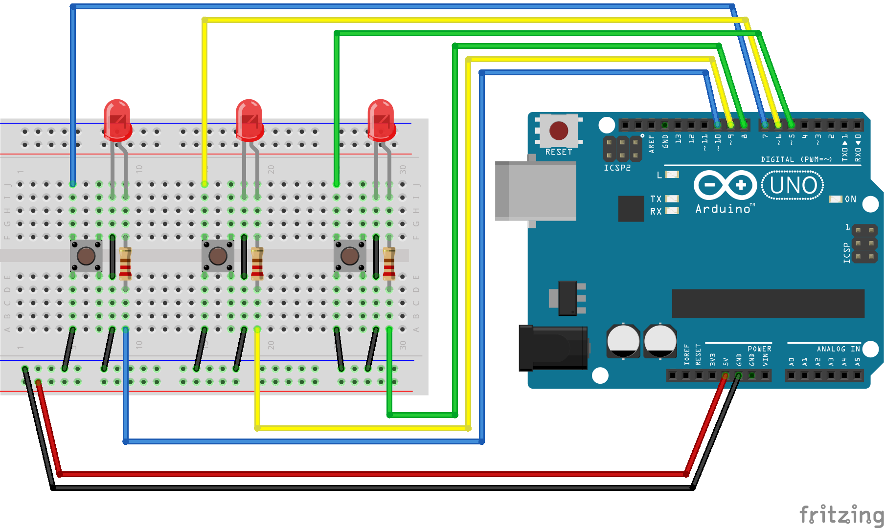
- Arduino
- LED * 3
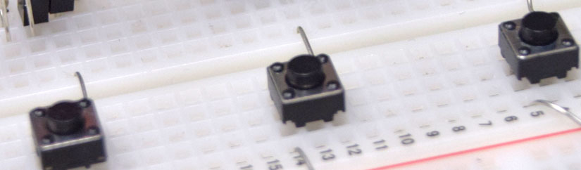
- Tact switch (momentary) * 3
Sketches
1. ON / OFF LED for each individual switch
First of all, this is a sketch that turns on / off LEDs with each switches. You can control with each switch so that each LEDs reacts individually.
#define SW_NUM 3
#define PUSH_SHORT  700
#define PUSH_LIMIT  PUSH_SHORT + 10

const byte s_pin[SW_NUM] = {5, 6, 7};
const byte leds [SW_NUM] = {8, 9, 10};


void setup() {
  for (byte i = 0 ; i < SW_NUM ; i++)
  {
    pinMode(s_pin[i], INPUT_PULLUP);
    pinMode(leds[i], OUTPUT);
  }
}


void loop() {
  static bool led_stat[SW_NUM] = {0, 0, 0};

  for (byte i = 0 ; i < SW_NUM ; i++)
  {
    byte sw = BUTTON(i);
    if (sw == 255) led_stat [i] = !led_stat [i];

    digitalWrite(leds[i], led_stat[i]);
  }
}


byte BUTTON(byte pin_num) {
  static unsigned short gauge[SW_NUM];

  byte sw_status = 0;

  //check switch status on or off
  if (!digitalRead(s_pin[pin_num]))
  {
    gauge[pin_num]++;
    gauge[pin_num] = min(gauge[pin_num], PUSH_LIMIT);
  } else {
    if (gauge[pin_num] >= PUSH_SHORT) sw_status = 255;
    gauge[pin_num] = 0;
  }

  //return value of switch status
  if (gauge[pin_num] >= PUSH_SHORT) sw_status = 1;

  return sw_status;
}
Commentary
Define the number of pins handled first by ‘SW_NUM’ and arrange the switch and LED digital pin numbers in the array according to the number. By the way, if you change here, you can increase the number of switches that can control.
#define SW_NUM 3
#define PUSH_SHORT  700
#define PUSH_LIMIT  PUSH_SHORT + 10

const byte s_pin[SW_NUM] = {5, 6, 7};
const byte leds [SW_NUM] = {8, 9, 10};
The main switch determination function “BUTTON” is processed by ‘if’ instead of ‘while’ statement. This make it possible to use multiple switch.
Preparing ‘gauge’ variable as each switch counter, increase counter if digitalRead is HIGH, reset if it is LOW. Also I defined ‘PUSH_LIMIT’ by ‘min’ function so that gauge counter does not increase too much.
byte BUTTON(byte pin_num) {
  static unsigned short gauge[SW_NUM];

  byte sw_status = 0;

  //check switch status on or off
  if (!digitalRead(s_pin[pin_num]))
  {
    gauge[pin_num]++;
    gauge[pin_num] = min(gauge[pin_num], PUSH_LIMIT);
  } else {
    if (gauge[pin_num] >= PUSH_SHORT) sw_status = 255;
    gauge[pin_num] = 0;
  }

  //return value of switch status
  if (gauge[pin_num] >= PUSH_SHORT) sw_status = 1;

  return sw_status;
}
Each switches conditions is shown on ‘sw_status’ variable.
If the gauge counter has reached the ‘PUSH_SHORT’ value, it judges to “pushed” and substitute 1.
if (gauge[pin_num] >= PUSH_SHORT) sw_status = 1;
If the switch released and the gauge has accumulated to some extent before resetting, it judges “pushed and released” and assign 255.
if (gauge[pin_num] >= PUSH_SHORT) sw_status = 255;
gauge[pin_num] = 0;
If there is nothing, it remains 0. It will pass those results as return values. That is, this “BUTTON” function indicates the state of the switches as,
| pushed | 1 |
| released | 255 |
| no push | 0 |
In the end, all you need is to make each behaves by its returned values.
void loop() {
  static bool led_stat[SW_NUM] = {0, 0, 0};

  for (byte i = 0 ; i < SW_NUM ; i++)
  {
    byte sw = BUTTON(i);
    if (sw == 255) led_stat [i] = !led_stat [i];

    digitalWrite(leds[i], led_stat[i]);
  }
}
At this point, it’s only actions when you release the switch. So, next step, I will introduce a sketch that the command changes by switch pushing duration.
2. With pushing time identification
It is the same that the LED turns on and off for each switch pushing. But it blinks when pressed for a while. Of course, each switch operated individually.
#define SW_NUM 3
#define PUSH_SHORT  700
#define PUSH_MID    20000
#define PUSH_LONG   100000
#define PUSH_LIMIT  PUSH_LONG + 10

const byte s_pin[SW_NUM] = {5, 6, 7};
const byte leds [SW_NUM] = {8, 9, 10};


void setup() {
  for (byte i = 0 ; i < SW_NUM ; i++)
  {
    pinMode(s_pin[i], INPUT_PULLUP);
    pinMode(leds[i], OUTPUT);
  }
  Serial.begin(38400);
}


void loop() {
  static bool led_stat[SW_NUM] = {0, 0, 0};

  for (byte i = 0 ; i < SW_NUM ; i++)
  {
    byte sw = BUTTON(i);

    bool  led_on = led_stat[i];
    short intval = 0;

    if (sw > 0) {
      if (sw == 255) led_stat [i] = !led_stat [i];
      else if (sw == 2) intval = 1000;
      else if (sw == 3) intval = 200;
      led_on = !led_on;
    }

    LEDS(i, led_on, intval);
  }
}


byte BUTTON(byte pin_num) {
  static unsigned long gauge[SW_NUM];

  byte sw_status = 0;

  //check switch status on or off
  if (!digitalRead(s_pin[pin_num]))
  {
    gauge[pin_num]++;
    gauge[pin_num] = min(gauge[pin_num], PUSH_LIMIT);
  } else {
    if (gauge[pin_num] >= PUSH_SHORT)
    {
      sw_status = 255;

      // head of checking push counter
      Serial.print((char)('A' + pin_num));
      Serial.print(":");
      Serial.println(gauge[pin_num]);
      // tail of checking push counter
    }
    gauge[pin_num] = 0;
  }

  //return value of switch status
  if (gauge[pin_num] >= PUSH_LONG) sw_status = 3;
  else if (gauge[pin_num] >= PUSH_MID) sw_status = 2;
  else if (gauge[pin_num] >= PUSH_SHORT) sw_status = 1;

  return sw_status;
}


void LEDS(byte pin_val, bool stat, unsigned short delay_time) {
  static unsigned long led_intval[SW_NUM];
  unsigned long led_dur = millis() - led_intval[pin_val];

  if (delay_time > 0)
  {
    if (led_dur >= delay_time) led_intval[pin_val] = millis();
    else if (led_dur > (delay_time / 2)) stat = !stat;
  }

  digitalWrite(leds[pin_val], stat);
}
Commentary
Basically just add constants according to your wishes.
Defines the length of switch by ‘#define’.
#define SW_NUM 3
#define PUSH_SHORT  700
#define PUSH_MID    20000
#define PUSH_LONG   100000
#define PUSH_LIMIT  PUSH_LONG + 10
Then, You can add pushing time patterns as you like by adding up in ‘BUTTON’ function. The difference of pushing time will be returned as 0-255 value by ‘sw_status’.
byte BUTTON(byte pin_num) {
  static unsigned long gauge[SW_NUM];

  byte sw_status = 0;

  //check switch status on or off
  if (!digitalRead(s_pin[pin_num]))
  {
    gauge[pin_num]++;
    gauge[pin_num] = min(gauge[pin_num], PUSH_LIMIT);
  } else {
    if (gauge[pin_num] >= PUSH_SHORT)
    {
      sw_status = 255;

      // head of checking push counter
      Serial.print((char)('A' + pin_num));
      Serial.print(":");
      Serial.println(gauge[pin_num]);
      // tail of checking push counter
    }
    gauge[pin_num] = 0;
  }

  //return value of switch status
  if (gauge[pin_num] >= PUSH_LONG) sw_status = 3;
  else if (gauge[pin_num] >= PUSH_MID) sw_status = 2;
  else if (gauge[pin_num] >= PUSH_SHORT) sw_status = 1;

  return sw_status;
}
It is completed by sorting the behavior by the return value from “BUTTON” function. Here we finally assign assignments to variables sent to the “LEDS” function.
void loop() {
  static bool led_stat[SW_NUM] = {0, 0, 0};

  for (byte i = 0 ; i < SW_NUM ; i++)
  {
    byte sw = BUTTON(i);

    bool  led_on = led_stat[i];
    short intval = 0;

    if (sw > 0) {
      if (sw == 255) led_stat [i] = !led_stat [i];
      else if (sw == 2) intval = 1000;
      else if (sw == 3) intval = 200;
      led_on = !led_on;
    }

    LEDS(i, led_on, intval);
  }
}
Adjust counting value
In this method, the amount of increasing counter changes depending on the interval time during which “BUTTON” is executed in the loop. In other words, you have to adjust the value of the ‘#define’ for your sketch length.
#define PUSH_SHORT  700
#define PUSH_MID    20000
#define PUSH_LONG   100000
#define PUSH_LIMIT  PUSH_LONG + 10
In the sample sketch below, the counter value of the pressed length is returns to the serial monitor.
// head of checking push counter
 Serial.print((char)('A' + pin_num));
 Serial.print(":");
 Serial.println(gauge[pin_num]);
// tail of checking push counter
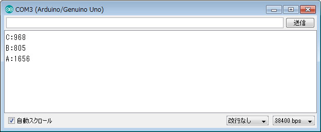
Please find proper value that makes it “long press”, “middle push”, “push” with your own project. I recommend that you final adjust again when your project is completed. I recommend you to comment out or delete this ‘Serial communication’ functions after adjustment. Because it affects the processing speed in loop.
If you use ‘delay’ function, it will cause the counter value to decrease greatly. So if you can’t avoid from ‘delay’ function on your sketch, it may be better to use ‘watchdog timer’.
Summary
This is simplified sample Sketch using ‘BUTTON’ function.
#define SW_NUM 3
#define PUSH_SHORT  700
#define PUSH_MID    20000
#define PUSH_LONG   100000
#define PUSH_LIMIT  PUSH_LONG + 10

const byte s_pin[SW_NUM] = {5, 6, 7};  // digital pins for Switches

/* use in setup()
 for (byte i = 0 ; i < SW_NUM ; i++) pinMode(s_pin[i], INPUT_PULLUP);
*/

byte BUTTON(byte pin_num) {
  static unsigned long gauge[SW_NUM];

  byte sw_status = 0;

  //check switch status on or off
  if (!digitalRead(s_pin[pin_num]))
  {
    gauge[pin_num]++;
    gauge[pin_num] = min(gauge[pin_num], PUSH_LIMIT);
  } else {
    if (gauge[pin_num] >= PUSH_SHORT)
    {
      sw_status = 255;

      // head of checking push counter - comment out on normal running
      Serial.print((char)('A' + pin_num));
      Serial.print(":");
      Serial.println(gauge[pin_num]);
      // tail of checking push counter
    }
    gauge[pin_num] = 0;
  }

  //return value of switch status
  if (gauge[pin_num] >= PUSH_LONG) sw_status = 3;
  else if (gauge[pin_num] >= PUSH_MID) sw_status = 2;
  else if (gauge[pin_num] >= PUSH_SHORT) sw_status = 1;

  return sw_status;
}